Control device and control method for internal combustion engine

Inactive Publication Date: 2017-09-14
TOYOTA JIDOSHA KK
View PDF7 Cites 4 Cited by
  • Summary
  • Abstract
  • Description
  • Claims
  • Application Information

AI Technical Summary

Benefits of technology

[0013]According to the configuration described above, a calculation load applied to the control device performing online calculation using the predictive

Problems solved by technology

However, the arithmetic capacity of the control device mounted on the vehicle is not as large as the amount of calculation required for the online calculation using the predictive model.
Accordingly, an calculation load on the control device may become large in a ca

Method used


Image

  • Control device and control method for internal combustion engine
  • Control device and control method for internal combustion engine
  • Control device and control method for internal combustion engine

Examples


Example

[0029]Firstly, a first embodiment of the invention will be described with reference to FIGS. 1 to 9.

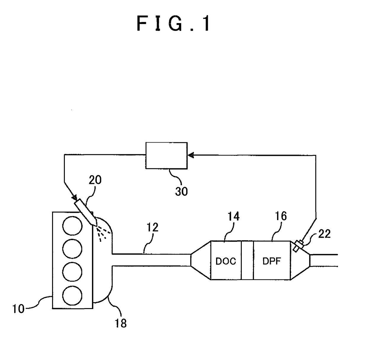
[0030]A control device according to the first embodiment controls an aftertreatment system for an internal combustion engine that is mounted on a vehicle. FIG. 1 is a schematic diagram illustrating the configuration of the aftertreatment system for the internal combustion engine. The aftertreatment system that is illustrated in FIG. 1 is provided with a diesel engine 10 as the internal combustion engine, a diesel oxidation catalyst (DOC) 14 and a diesel particulate filter (DPF) 16 disposed in an exhaust passage 12 of the diesel engine 10, a fuel addition device 20 disposed in an exhaust port 18, and a temperature sensor 22 disposed downstream from the DPF 16. The DOC 14 is a catalyst that converts the hydrocarbon (HC) and carbon monoxide (CO) contained in exhaust gas into water (H2O) and carbon dioxide (CO2) by oxidation. The DPF 16 is a filter that collects the particulate components...

Example

[0060]Hereinafter, the second embodiment of the invention will be described with reference to FIGS. 10 to 13. The following description of the second embodiment assumes, as in the description of the first embodiment, that the aftertreatment system for a diesel engine is the controlled object and the ECU 30 has a target value compliance control structure similar to that of the first embodiment. Accordingly, the following description will focus on how the second embodiment differs from the first embodiment.

[0061]FIG. 10 is a diagram for showing a problem of the first embodiment. In the numerical simulation that is illustrated in FIG. 7, the target value Tdpfref of the DPF bed temperature is assumed to be constant during the simulation period. However, the target value Tdpfref should rise from moment to moment during the actual heating control for the DPF 16 as a result of a rise in DPF bed temperature. FIG. 10 shows the result of a numerical simulation performed in view of this point....


PUM


Abstract

A control device includes a feedback controller that determines an operation amount of an actuator by feedback control such that an actual value of a state quantity becomes closer to a target value, and a reference governor that modifies the target value such that an amount of change in the state quantity per unit time is equal to or less than an upper limit value β. The reference governor calculates a modified target value by adding one of 2ζβ/ωn and β/{(T2/T1)T<sub2>2</sub2>/(T<sub2>1</sub2>−T<sub2>2</sub2>)−(T2/T1)T<sub2>1</sub2>/(T<sub2>1</sub2>−T<sub2>2</sub2>)} to a current value of the state quantity (ζ, ωn: an attenuation coefficient, a natural angular frequency of a model formula in a case where a dynamic characteristic of a closed-loop system is modeled as a dead time plus second-order vibration system, T1, T2 =−ωn−1(−ζ±√{square root over ((ζ2−1))}−1), and determines the smaller one of the modified target value and an original target value as a final target value of the state quantity.

Description

BACKGROUND OF THE INVENTION[0001]1. Field of the Invention[0002]The invention relates to a control device and a control method for an internal combustion engine.[0003]2. Description of Related Art[0004]In general, a control device for an internal combustion engine is configured to determine a control input for the internal combustion engine by feedback control such that an output value of a control amount complies with a target value, in a case where the target value is given with regard to the control amount for the internal combustion engine. In many cases of actual internal combustion engine control, however, various hardware or control constraints are present with regard to the state quantity of the internal combustion engine. In a case where these constraints are not satisfied, hardware malfunctioning and a decline in control performance may occur. The capability of satisfying the constraints as well as the capability of the output value complying with the target value is one o...

Claims


Application Information

Patent Timeline
IPC IPC(8): F02D41/02F01N3/021F02D41/14
CPCF02D41/0235F01N2900/1602F01N3/021F02D41/1401F02D41/027F02D2200/0804F02D2041/1433F02D41/02
Inventor NAKADA, HAYATO
Owner TOYOTA JIDOSHA KK
Why Eureka
Try Eureka