Fuel rail for gasoline direct-injection engine

a direct injection and fuel rail technology, applied in the direction of machines/engines, fuel injection apparatus, charge feed systems, etc., can solve the problems of high cost required for part replacement, and large labor and time, so as to facilitate the work of part replacement and drastically reduce the cost of part replacement.

Inactive Publication Date: 2017-09-14
USUI KOKUSAI SANGYO KAISHA LTD
View PDF4 Cites 5 Cited by
  • Summary
  • Abstract
  • Description
  • Claims
  • Application Information

AI Technical Summary

Benefits of technology

[0010]A fuel rail for a gasoline direct-injection engine in accordance with the present invention employs a way of attaching a branch connector through a recessed connection member using a thread fastening mechanism, or a recessed connection member using a bolt fastening mechanism, as a mechanism for attaching the branch connector to a main pipe, and also employs an O-ring sealing as a sealing mechanism. The fuel rail has a structure in which an O-ring provided between the recessed connection member and the branch connector is tightened by an axial force created by the tightening of the branch connector that is screwed and fastened to the recessed connection member, or by an...

Problems solved by technology

Accordingly, it takes a lot of labor and time to replace the part and it is necessary to arrange a set of a fuel rail as a part to be replaced, which causes a problem that the cost required for part replacement is high.
Further, when the hardness of the branch pipe 23 is lower...

Method used


Image

  • Fuel rail for gasoline direct-injection engine
  • Fuel rail for gasoline direct-injection engine
  • Fuel rail for gasoline direct-injection engine

Examples


first embodiment

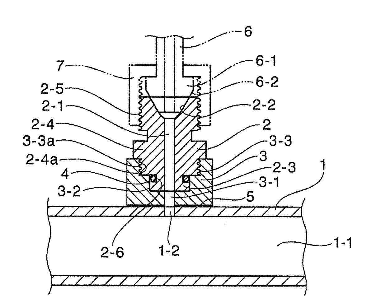
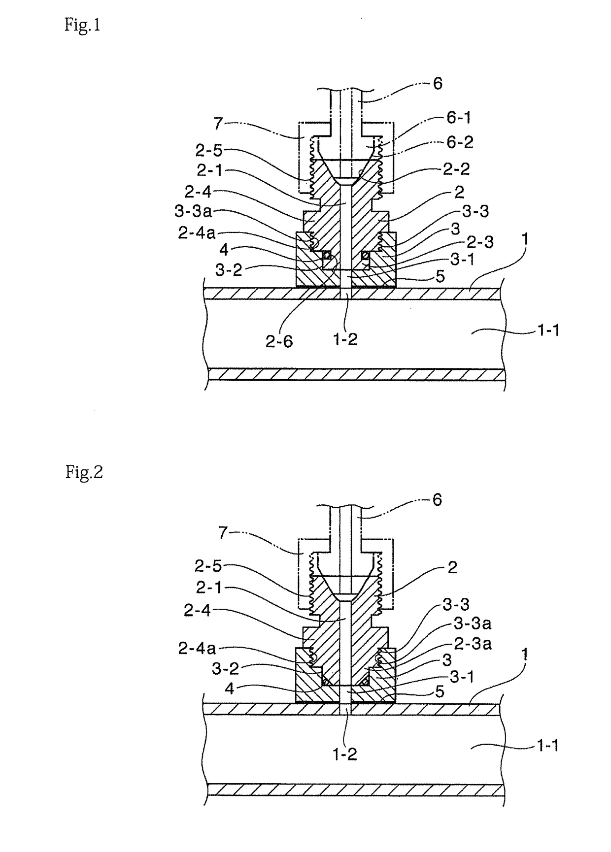
[0018]A fuel rail for a gasoline direct-injection engine of a first embodiment illustrated in FIG. 1 has the following structure. That is, a recessed connection member 3 having at a central portion thereof a communicating hole 3-1 communicating with a through-hole 1-2, which is pierced in a circumferential wall portion in an axial direction of a main pipe 1 that is formed of a pipe made of steel or stainless steel and has a flow passage 1-1 formed therein, is joined to the through-hole 1-2 by brazing or welding; a lower end portion of a branch connector 2 is recess-projection fitted to the recessed connection member 3 and is detachably fastened thereto by a thread fastening mechanism; and an O-ring 4 provided between the recessed connection member 3 and the branch connector 2 is tightened by an axial force created by the thread fastening of the branch connector 2 to thereby create a seal between the recessed connection member 3 and the branch connector 2.

[0019]In this regard, to fac...

third embodiment

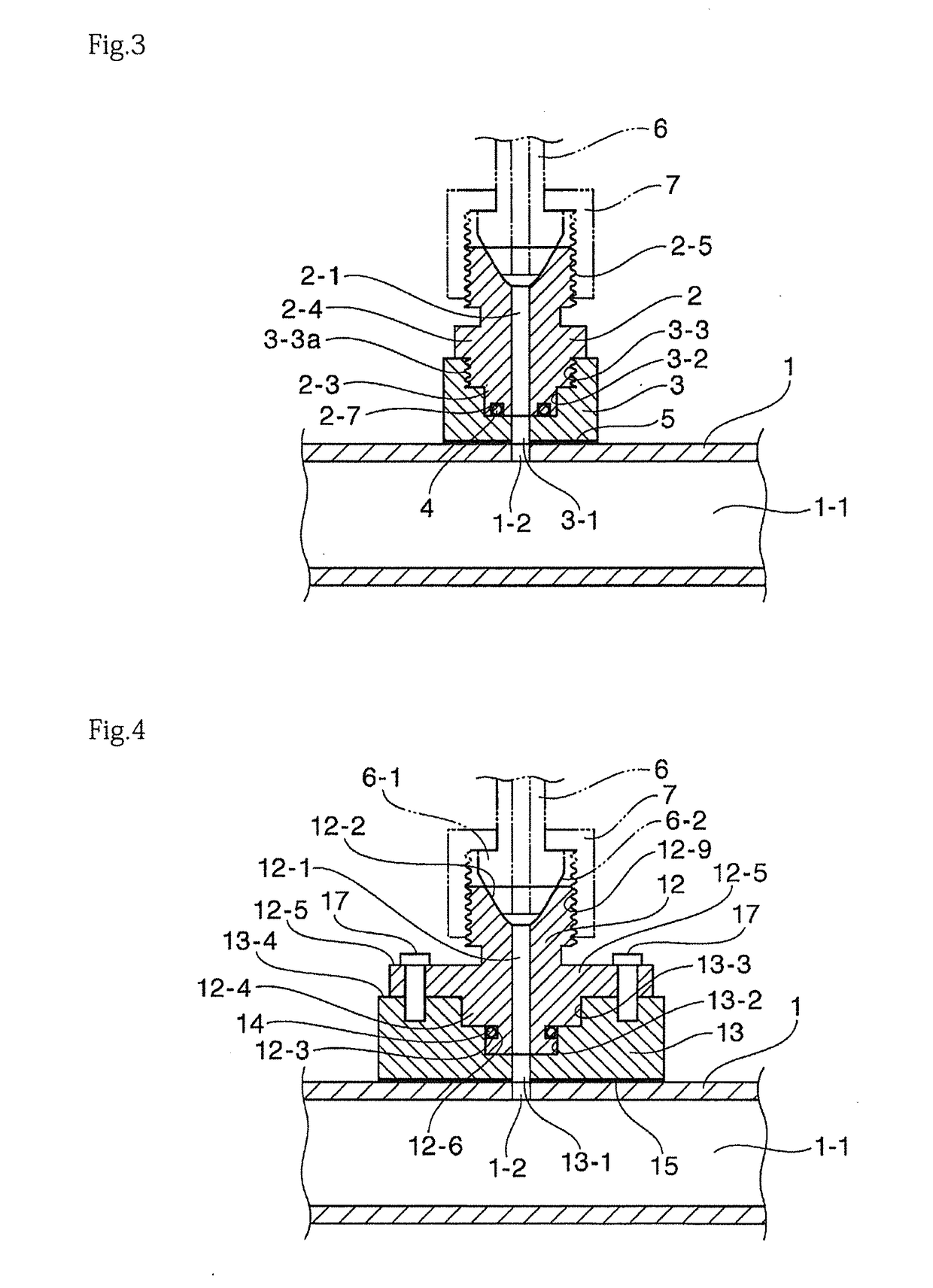
[0023]The fuel rail for the gasoline direct-injection engine of the third embodiment illustrated in FIG. 3 has the structure, in which the O-ring 4 is attached to an annular groove 2-7 which is formed at a lower end face of the small-diameter cylinder portion 2-3 of the branch connector 2 to be recess-projection fitted to the small-diameter hole portion 3-2 of the recessed connection member 3 that is joined to the main pipe 1 by brazing or welding, and the O-ring 4 is tightened by the axial force created by the thread fastening of the branch connector 2, to thereby create a seal between the branch connector 2 and the recessed connection member 3. Also in this seal structure, the stability and reliability of the seal are ensured, as in the fuel rails for gasoline direct-injection engines illustrated in FIGS. 1 and 2.

fourth embodiment

[0024]A fuel rail for a gasoline direct-injection engine of a fourth embodiment illustrated in FIG. 4 has the following structure. That is, a recessed connection member 13 having at a central portion thereof a communicating hole 13-1 communicating with the through-hole 1-2, which is pierced in the circumferential wall portion in the axial direction of the main pipe 1 that is formed of a pipe made of steel or stainless steel and has the flow passage 1-1 formed therein, is joined to the through-hole 1-2 by brazing or welding; a lower end portion of a branch connector 12 is recess-projection fitted to the recessed connection member 13 and is detachably fastened thereto by a bolt fastening mechanism; and an O-ring 14 provided between the recessed connection member 13 and the branch connector 12 is tightened by the axial force created by the fastening of the branch connector 12 to thereby create a seal between the recessed connection member 13 and the branch connector 12.

[0025]In this re...


PUM


Abstract

Provided is a fuel rail for a gasoline direct-injection engine, characterized in that a branch connector is attached to a main pipe through a recessed connection member, the recessed connection member is secured to the main pipe by brazing or welding, the branch connector is recess-projection fitted to the recessed connection member and is detachably fastened thereto by a thread fastening mechanism or by a bolt fastening mechanism, and an O-ring provided between the recessed connection member and the branch connector is tightened by an axial force created by fastening of the branch connector to thereby create a seal between the recessed connection member and the branch connector; and a hardness of the branch connector is set to be lower than that of the branch pipe facing the branch connector.

Description

BACKGROUND[0001]1. Field of the Invention[0002]The present invention relates to a fuel rail for supplying a high-pressure fuel, which is supplied from a fuel booster pump of an electronic fuel injection-type automobile engine or the like, through a fuel injector (an injection nozzle) directly injecting the fuel into an engine cylinder, and more particularly, the invention relates to a fuel rail for a gasoline direct-injection engine having a structure in which a branch connector (a connection nipple or an inlet) is attached to a main pipe.[0003]2. Description of the Related Art[0004]Known are conventional fuel rails for gasoline direct-injection engines of this type including: a fuel rail including a main pipe and a branch connector (a connection nipple or an inlet) which are integrally formed by a forging method, and a fuel rail having a structure in which a branch connector is connected to a main pipe by welding or brazing. Among these fuel rails, a typical fuel rail for a gasolin...

Claims


Application Information

Patent Timeline
IPC IPC(8): F02M55/02F02M37/00
CPCF02M37/0017F02M55/025F02M55/005F02M55/02
Inventor SUZUKI, MASARUSUZUKI, SHUJIHAYASHI, KOICHI
Owner USUI KOKUSAI SANGYO KAISHA LTD
Why Eureka
Try Eureka