Bidirectional isolated multi-level dc-dc converter and method thereof

a dc-dc converter and multi-level technology, applied in the direction of dc-dc conversion, power conversion systems, instruments, etc., can solve the problems of high ripple quantity, low efficiency, high electromagnetic interference, etc., and achieve the effect of reducing manufacturing cost, minimizing dimensions, and enhancing operational efficiency

Active Publication Date: 2017-09-14
ABLEREX ELECTRONICS CO LTD
View PDF0 Cites 5 Cited by
  • Summary
  • Abstract
  • Description
  • Claims
  • Application Information

AI Technical Summary

Benefits of technology

[0011]The primary objective of this invention is to provide a bidirectional isolated multi-level DC-DC converter and control method thereof for boost mode. The DC-DC converter includes a low voltage side and a high voltage side. In boost mode, a plurality of low-voltage side switches are operated with a first fixed duty cycle which is greater than 0.5 while a plurality of first high-voltage side switches and a plurality of second high-voltage side switches are switched off. Furthermore, a plurality of first diodes of the first high-voltage side switches and a plurality of second diodes of the second high-voltage side switches are conducted and a bidirectional switch is switched on and off to control a first DC output voltage at the high voltage side. Advantageously, the bidirectional isolated multi-level DC-DC converter and conversion method of the present invention is successful in minimizing the dimensions, reducing the manufacturing cost and enhancing the operational efficiency.

Problems solved by technology

Even though the conventional isolated DC-DC converter has a specific advantageous of simple and easy control, it has several drawbacks in operation, including low efficiencies, high ripple quantities, high electromagnetic interference and requiring the use of a filter circuit with a large capacity.
However, the above-mentioned multi-level DC-DC converter 9 has several drawbacks, including a sophisticated structure at the high voltage side of the transformer 90, an increase of total manufacturing cost and dimensions and unidirectional power transmission.

Method used


Image

  • Bidirectional isolated multi-level dc-dc converter and method thereof
  • Bidirectional isolated multi-level dc-dc converter and method thereof
  • Bidirectional isolated multi-level dc-dc converter and method thereof

Examples


Embodiment Construction

[0092]It is noted that a bidirectional isolated multi-level DC-DC converter, operation method and control method thereof in accordance with the preferred embodiment of the present invention can be applicable to various multi-level DC-DC converters or other equivalent devices, which are not limitative of the present invention.

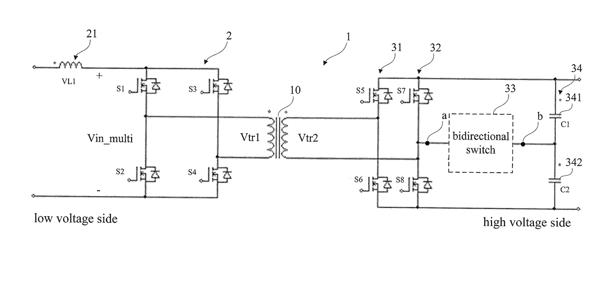
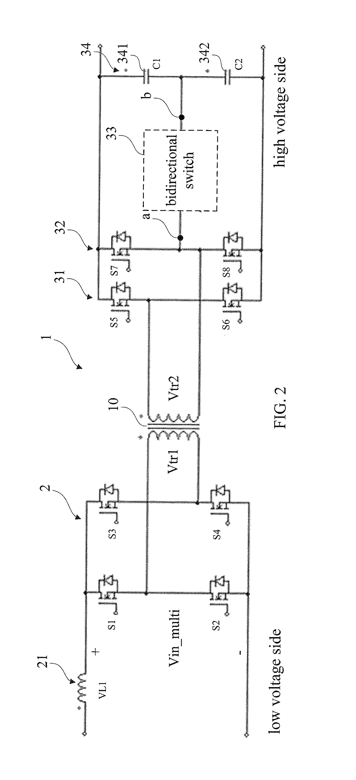
[0093]FIG. 2 shows a schematic view of a bidirectional isolated multi-level DC-DC converter in accordance with a first preferred embodiment of the present invention. Referring now to FIG. 2, the bidirectional isolated multi-level DC-DC converter 1 in accordance with the first preferred embodiment of the present invention includes a transformer 10, a plurality of low-voltage side switches 2, an inductor 21, a plurality of first high-voltage side switches 31, a second high-voltage side switches 32, a bidirectional switch 33 and a capacitor set 34.

[0094]With continued reference to FIG. 2, by way of example, the bidirectional isolated multi-level DC-DC converter 1 i...


PUM

PropertyMeasurementUnit
voltageaaaaaaaaaa
capacitanceaaaaaaaaaa
DC output voltageaaaaaaaaaa

Abstract

A DC-DC converter is operated in a boost mode by operating a plurality of low-voltage side switches with a first fixed duty cycle (greater than 0.5), with cutting off a plurality of the first high-voltage side switches and a plurality of the second high-voltage side switches, with conducting a plurality of the first diodes of the first high-voltage side switches and a plurality of the second diodes of the second high-voltage side switches, and with alternatively conducting and cutting off a bidirectional switch. In a buck mode, the low-voltage side switches are cut off and a plurality of diodes of the low-voltage side switches are conducted. Furthermore, the first high-voltage side switches are complemented and are operated with a second fixed duty cycle (less than 0.5) while the second high-voltage side switches are conducted and cut off alternatively and the bidirectional switch is switched on and off.

Description

BACKGROUND OF THE INVENTION[0001]1. Field of the Invention[0002]The present invention relates to a bidirectional isolated multi-level DC-DC converter and control method thereof. Particularly, the present invention relates to the bidirectional isolated multi-level DC-DC converter and control method thereof for reducing the dimensions.[0003]2. Description of the Related Art[0004]Generally, a conventional isolated DC-DC converter has been widely used in various industrial fields. Even though the conventional isolated DC-DC converter has a specific advantageous of simple and easy control, it has several drawbacks in operation, including low efficiencies, high ripple quantities, high electromagnetic interference and requiring the use of a filter circuit with a large capacity. Conversely, a conventional multi-level DC-DC converter has several advantageous of relatively higher efficiencies, relatively lower electromagnetic interference and allowing the use of a filter circuit with a relati...

Claims


Application Information

Patent Timeline
Patent Type & Authority Applications(United States)
IPC IPC(8): H02M3/335H02M1/08
CPCH02M3/33546H02M3/33553H02M1/08H02M3/33507H02M3/33584
Inventor CHIANG, WEN-JUNGHUANG, KUO-FANGCHEN, WEN-CHUNG
Owner ABLEREX ELECTRONICS CO LTD
Why Eureka
Try Eureka