
Liquid discharge apparatus and head unit

a liquid discharge apparatus and head unit technology, applied in the direction of printing mechanisms, spacing mechanisms, printing, etc., can solve the problems of high power consumption and heat generation, deterioration of printing quality, and distortion of driving signals which are transferred by cables, so as to reduce faults, suppress abnormal operations, and efficiently cool

Active Publication Date: 2017-09-21
SEIKO EPSON CORP
View PDF6 Cites 1 Cited by
  • Summary
  • Abstract
  • Description
  • Claims
  • Application Information

AI Technical Summary

Benefits of technology

The present invention proposes a liquid discharge apparatus and head unit that can prevent faults caused by liquid mist attached to the drive circuit. This improves the reliability of the apparatus.

Problems solved by technology

In this liquid discharge apparatus, it is necessary for the length of the cable to be double or more of the scanning width of the carriage, and there are problems in that the waveforms of the driving signals which are transferred by the cable become distorted and printing quality deteriorates due to the effects of static electricity which is generated due to the cable rubbing against the members inside a casing and various types of external noise such as electrostatic noise which is easily picked up due to the antenna effect with the cable being in the shape of a loop.
However, power consumption and the amount of heat generation are high due to the large currents flowing through the class AB amplifier, and the size and mounting weight of the carriage is increased due to it being necessary to mount a heat sink for releasing heat on the carriage.
As a result, there are problems in that the power consumption of the drive circuit and the power consumption of the motor for scanning the carriage back and forth increase and energy savings and durability of the liquid discharge apparatus deteriorate due to the load on the motor increasing and the life of the motor being shortened.
There is a problem in that a portion of the ink which is discharged turns into mist and is suspended in air and becomes attached to various locations in the casing, and it is easy for the ink mist to become adhered to the drive circuit which operates using high voltages in order to drive the piezoelectric elements.
The ink mist is conductive due to also including components other than water, and there is a risk that as a result of unforeseen short circuit paths being generated in a case where the mist which becomes attached to the drive circuit condenses and forms a conductive liquid film, driving of the piezoelectric elements will stop or unforeseen faults will be generated such as erroneous discharging of ink.
On the other hand, it is relatively difficult for liquid which turns into mist to be retained in a direction in which the carriage moves from the home position due to the space for the carriage to move being wide.

Method used


Image

  • Liquid discharge apparatus and head unit
  • Liquid discharge apparatus and head unit
  • Liquid discharge apparatus and head unit

Examples


first embodiment

1. First Embodiment

1-1. Liquid Discharge Apparatus Concept

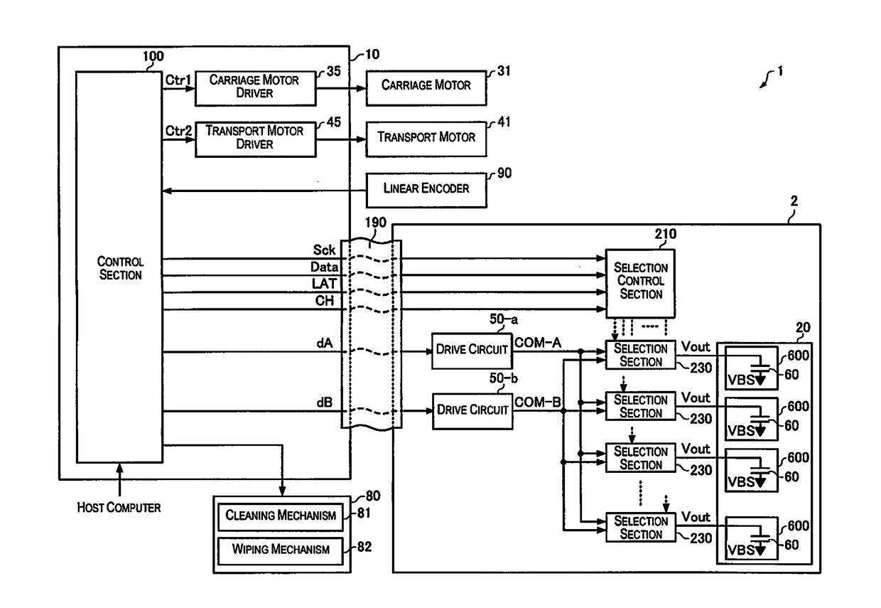
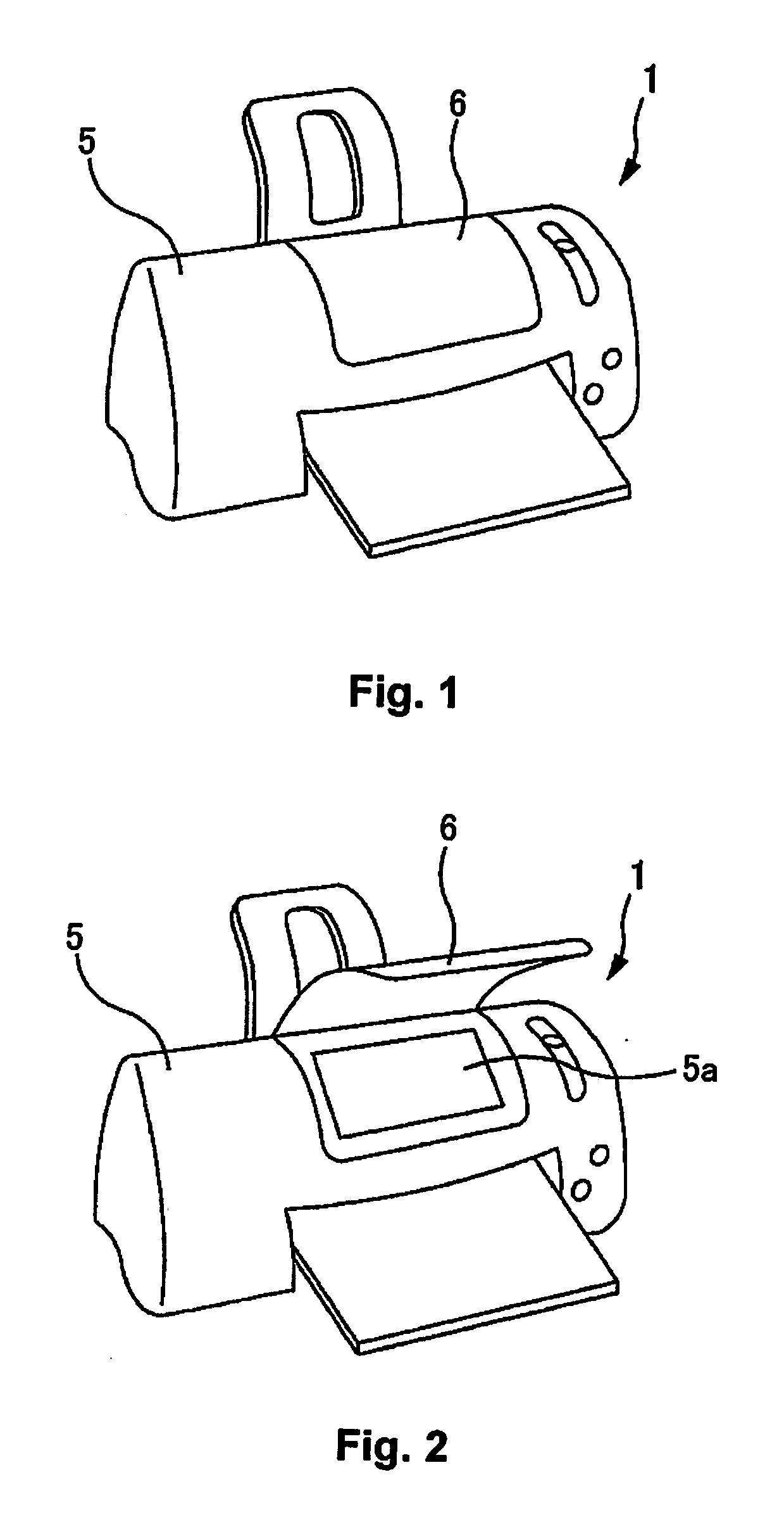
[0079]A printing apparatus which is one example of a liquid discharge apparatus as in the present embodiment is an ink jet printer which forms groups of ink dots on a printing medium such as paper by ink being discharged in accordance with image data which is supplied from an external host computer, and due to this, prints images (which includes text, diagrams, and the like) according to the image data.

[0080]Here, it is possible for examples of the liquid discharge apparatus to include, for example, a printing apparatus such as a printer, a colorant material discharge apparatus which is used in manufacturing color filters such as for a liquid crystal display, an electrode material discharge apparatus which is used in forming electrodes for an organic EL display, a field emission display (FED), and the like, a biological organic matter discharge apparatus which are used in bio-chip manufacture, a stereoscopic molding apparatus...

second embodiment

2. Second Embodiment

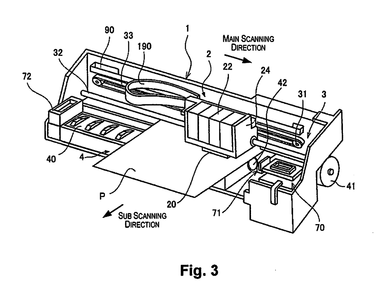
[0220]As a result of there being a large number of the nozzles 651 in the liquid discharge apparatus 1 in order to realize high-speed printing and high-precise printing, there is an extremely large amount of ink which is discharged per unit of time in the printing operation. Since a portion of the ink which is discharged during printing turns into mist, most of the ink mist is suspended in inner sections of the casing 5, and it is easy for the ink mist which is suspended to gather in spaces which are close to the inner wall surfaces which are at both ends of the casing 5 due to effects of wind pressure which are generated in the movement direction of the carriage 24 (the main scanning direction) being imparted in accompaniment with movement of the carriage 24. Then, since the home position where the carriage 24 is positioned when in standby without the head 20 performing an ink (liquid) discharge operation is provided close to the inner wall surface of the casing...

third embodiment

4. Third Embodiment

[0233]The liquid discharge apparatus 1 as in a fourth embodiment has a configuration in the same manner as the liquid discharge apparatus 1 as in the first embodiment, the second embodiment, and the third embodiment, and has the characteristic in that supply openings 661 are further provided. Below, the description which overlaps with the first embodiment, the second embodiment, and the third embodiment is omitted or simplified and mainly the content which is different to the first embodiment, the second embodiment, and the third embodiment will be described.

[0234]FIG. 22 is a planar diagram of the head 20 in a fourth embodiment viewed from the discharge surface 20a side (the printing medium P side). Nozzle plates 632a to 632h are provided in the discharge surface 20a of the head 20 as shown in FIG. 22.

[0235]A plurality of nozzles 651a are arranged in the nozzle plate 632a in one row in the sub scanning direction, and the head unit 2 is provided with a discharge s...


PUM


Abstract

A liquid discharge apparatus has a head provided with discharge sections which discharge a liquid, a drive circuit configured to generate driving signals for driving the discharge sections and discharging the liquid, a carriage mounted with the head and the drive circuit, a motor configured to move the carriage, and a flushing box configured and arranged to receive the liquid discharged from the discharge sections. The drive circuit is mounted at a position so as not to pass above the flushing box while the carriage is being moved.

Description

CROSS-REFERENCE TO RELATED APPLICATIONS[0001]This application claims priority to Japanese Patent Application No. 2016-054439 filed on Mar. 17, 2016. The entire disclosure of Japanese Patent Application No. 2016-054439 is hereby incorporated herein by reference.BACKGROUND[0002]Technical Field[0003]The present invention relates to a liquid discharge apparatus and a head unit.[0004]Related Art[0005]It is known that piezoelectric elements (for example, a piezo element) are used in discharge liquid apparatuses such as ink jet printers which print images and text by discharging ink. The piezoelectric elements are provided to correspond to a plurality of nozzles in a recording head (an ink jet head) and dots are formed by specific amounts of ink (liquid) being discharged at specific timings from the nozzles due to each of the piezoelectric elements being driven in accordance with driving signals. In consideration of electricity, since the piezoelectric elements have a capacitive load such ...

Claims


Application Information

Patent Timeline
Patent Type & Authority Applications(United States)
IPC IPC(8): B41J2/045
CPCB41J2/04586B41J2/04541B41J2/07B41J2/04505B41J2/04548B41J2/04581B41J2/04588B41J2/04593B41J2/16517B41J2/16526B41J19/005B41J29/13B41J29/38
Inventor TAMURA, NOBORUMATSUYAMA, TORU
Owner SEIKO EPSON CORP
Learn More