Supercharge Your Innovation With Domain-Expert AI Agents!

Automotive collision avoidance sensor system

Inactive Publication Date: 2017-09-21
CHARTER IP
View PDF10 Cites 3 Cited by
  • Summary
  • Abstract
  • Description
  • Claims
  • Application Information

AI Technical Summary

Benefits of technology

The patent describes a sensor system that helps avoid collisions in cars. It has two lenses and a laser that sends a beam of light to the front and back of the car. The laser then collects the light that comes back and converts it into electrical signals. A computer analyzes these signals to create a real-time 3D map of the car's surroundings. This allows the system to constantly measure and update its safety metrics to prevent collisions. Overall, this system helps make cars safer by giving drivers a better view of their surroundings.

Problems solved by technology

Currently, the known LWR's are limited in sensitivity, range, spectral coverage (e.g., range of wavelengths detectible by the LWR system), angular coverage, operating temperature, resolution, etc.
Moreover, current LWR devices are large and / or bulky and consume large amounts of power.
This makes the known LWR systems unsuitable for many applications in which they would otherwise be useful.
Furthermore, the known LWR's are prone to false alarms due to ambient light and / or other sources of optical emissions, which are common in the environment.
These are cumbersome and expensive ($65,000) systems, typically sitting 4 feet above the driver line of sight, and utilizing several rotating lenses in an effort to build a picture of the 3D environment around the car.
The sensitivity of these sensors is also poor, particularly degrading in poor weather / visibility conditions (fog, snow, rain, etc.).
Moreover, these current LiDAR systems are limiting in terms of their actual capability, and can only see a swath or narrow beam angle at a time.
So instead of a complete 360 degree view, a series of cylindrical views are fed into a computation engine, thus it is a very computation-intensive system.
Therefore, these system cannot provide the 3D picture at every instant as can the human brain, being limited by the frame rate (typically 10-60 Hz) which is way too slow a reaction / refresh time.

Method used


Image

  • Automotive collision avoidance sensor system
  • Automotive collision avoidance sensor system
  • Automotive collision avoidance sensor system

Examples


Embodiment Construction

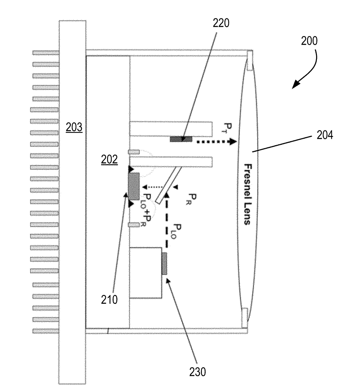
[0033]Before delving into Applicant's novel automotive collision avoidance system, Applicants provides the background of their electromagnetic or laser warning sensor as described in the co-pending '607 application. In the following description, certain specific details are set forth in order to provide a thorough understanding of various example embodiments of the disclosure. However, one skilled in the art will understand that the disclosure may be practiced without these specific details. In other instances, well-known structures associated with manufacturing techniques have not been described in detail to avoid unnecessarily obscuring the descriptions of the example embodiments of the present disclosure.

[0034]Unless the context requires otherwise, throughout the specification and claims that follow, the word “comprise” and variations thereof, such as “comprises” and “comprising,” are to be construed in an open, inclusive sense, that is, as “including, but not limited to.”

[0035]R...


PUM


Abstract

In an automotive collision avoidance sensor system installed at both the fore and aft of a vehicle, there is provided an output lens, an input lens, and a transmit laser. The transmit laser is adapted to transmit a pulsed beam through the output lens to impact roadway, surrounding vehicles or objects fore, aft, port and starboard of the vehicle, with return signals from the roadway, surrounding vehicles or objects reflecting off the input lens. A sensor of the system adapted collects the return signals from the input lens to convert them into output voltages and signals, and has a data processor configured to analyze the output voltages and signals so as to calculate real-time 3-dimensional situation awareness measurements and safety metrics which are constantly measured and updated to prevent possible collision.

Description

CROSS-REFERENCE TO RELATED APPLICATIONS[0001]The present application claims priority under 35 U.S.C. §120 to U.S. patent application Ser. No. 14 / 218,607, filed Mar. 18, 2014 to Aina et al. (pending / allowed) which is herein incorporated by reference in its entirety.BACKGROUND[0002]Field[0003]The example embodiments in general are directed to an automotive collision avoidance sensor system.[0004]Related Art[0005]Lasers or other forms of coherent electromagnetic radiation (ER) today have numerous applications, such as applications for marking and guiding munitions, vehicles, determining distance (ranging), navigating, surveying, remote sensing, highlighting an object and so on. In response, laser warning receiver (LWR) systems have become important to detect and process laser emissions. Typically, a LWR is a passive system that detects incoming laser emissions and processes the incoming laser emissions for various parameters, such as range of the origin or source of the laser emissions...

Claims


Application Information

Patent Timeline
IPC IPC(8): G06K9/00G01S7/48
CPCG06K9/00805G01S7/4804G01S2013/9378B60T2210/32G01S2013/9375B60T2201/022G01S3/781G01S3/784G01S17/10G01S7/4816G01S7/4873G01S17/931G01S17/894G06V20/58
Inventor AINA, OLALEYE A.
Owner CHARTER IP
Features
  • R&D
  • Intellectual Property
  • Life Sciences
  • Materials
  • Tech Scout
  • Unparalleled Data Quality
  • Higher Quality Content
  • 60% Fewer Hallucinations
Learn More