Simplified transversal induction sealing device
- Summary
- Abstract
- Description
- Claims
- Application Information
AI Technical Summary
Benefits of technology
Problems solved by technology
Method used
Image
Examples
second embodiment
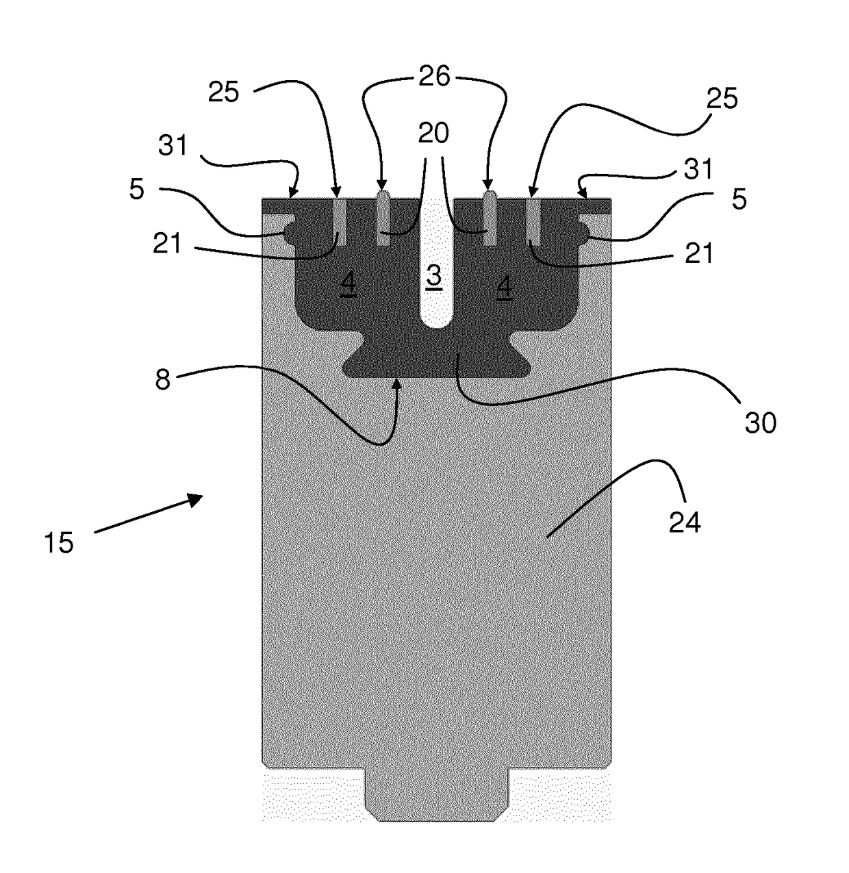
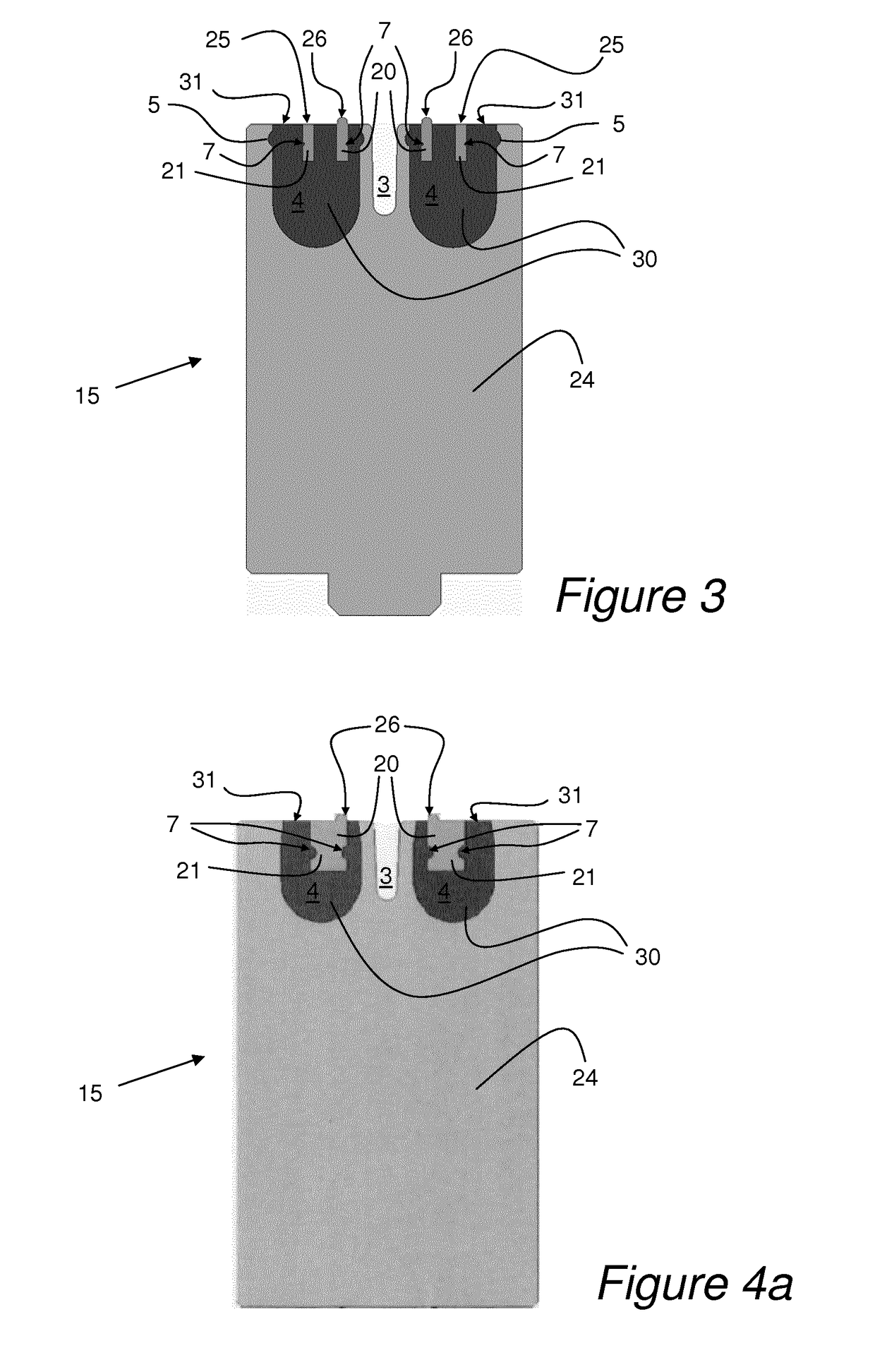
[0043]FIG. 3 shows a cross sectional view of a transversal induction device 19 according to the present invention. A supporting body 24 has two cavities 4, in which cavities 4 inductor device 20, 21 are positioned. In each cavity 4 a flux-concentrating insert 30 is moulded around the respective inductions means 20, 21, without covering the active surfaces 25, 26 of the respective inductor device. The flux-concentrating insert has an interacting surface 31 that is in level with the active surface 25 of the inductor device 20, 21. Each cavity has a circumferential recess 5 along a side wall for locking the moulded flux-concentrating insert 30 in the cavity. The flux-concentrating insert 30 is moulded by a magnetic compound of a polymer and soft magnetic particles. A cutting groove 3 is formed in the supporting body 24 between the two cavities 4 to allow a packing material to be cut simultaneously with the sealing of a packing material on either side of the cutting groove 30. Each of t...
third embodiment
[0044]FIG. 4a shows a cross sectional view of a transversal induction device 19 according to the present invention. A supporting body 24 has two cavities 4, in which cavities 4 inductor device 20, 21 are positioned. In each cavity 4 a flux-concentrating insert 30 is moulded around the respective inductions means 20, without covering the active surfaces 26 of the respective inductor device. The flux-concentrating insert has an interacting surface 31 that is in level with the lower part of the active surface 25 of the inductor device 20. The flux-concentrating insert 30 is moulded by a magnetic compound of a polymer and soft magnetic particles. A cutting groove 3 is formed in the supporting body 24 between the two cavities 4 to allow a packing material to be cut simultaneously with the sealing of a packing material on either side of the cutting groove 30. Each of the inductor device have two recesses 7 for locking each inductor device to the respective moulded flux-concentrating inser...
sixth embodiment
[0047]FIG. 5 shows a cross sectional view of a transversal induction device 19 according to the present invention. In this embodiment four cavities 4 are used. In each cavity 4 a flux-concentrating insert 30 is moulded around the respective inductions means 20. This embodiment is an example of how a so-called twin loop inductor can be combined with the present invention.
PUM
| Property | Measurement | Unit |
|---|---|---|
| Mechanical strength | aaaaa | aaaaa |
| Electrical conductor | aaaaa | aaaaa |
| Area | aaaaa | aaaaa |
Abstract
Description
Claims
Application Information
 - R&D
- Intellectual Property
- Life Sciences
- Materials
- Tech Scout
- Unparalleled Data Quality
- Higher Quality Content
- 60% Fewer Hallucinations
Browse by: Latest US Patents, China's latest patents, Technical Efficacy Thesaurus, Application Domain, Technology Topic, Popular Technical Reports.
© 2025 PatSnap. All rights reserved.Legal|Privacy policy|Modern Slavery Act Transparency Statement|Sitemap|About US| Contact US: help@patsnap.com


