
DC motor control device and game machine

Active Publication Date: 2017-09-28
ORMON CORP
View PDF7 Cites 2 Cited by
  • Summary
  • Abstract
  • Description
  • Claims
  • Application Information

AI Technical Summary

Benefits of technology

The present invention provides a DC motor control device and game machine that can manage the rotation of the motor within a large range without increasing the circuit size. This invention can suppress the circuit scale and make the device more efficient and compact.

Problems solved by technology

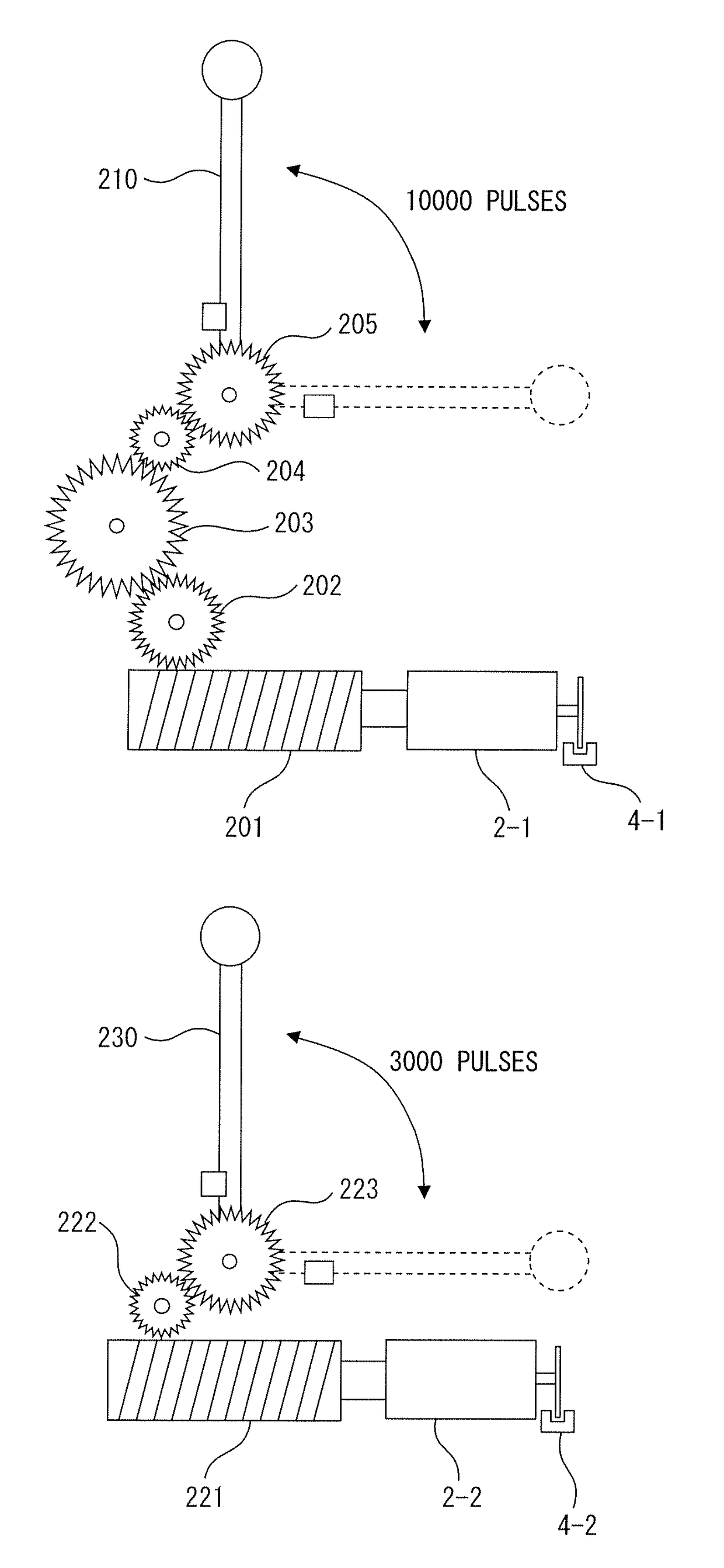
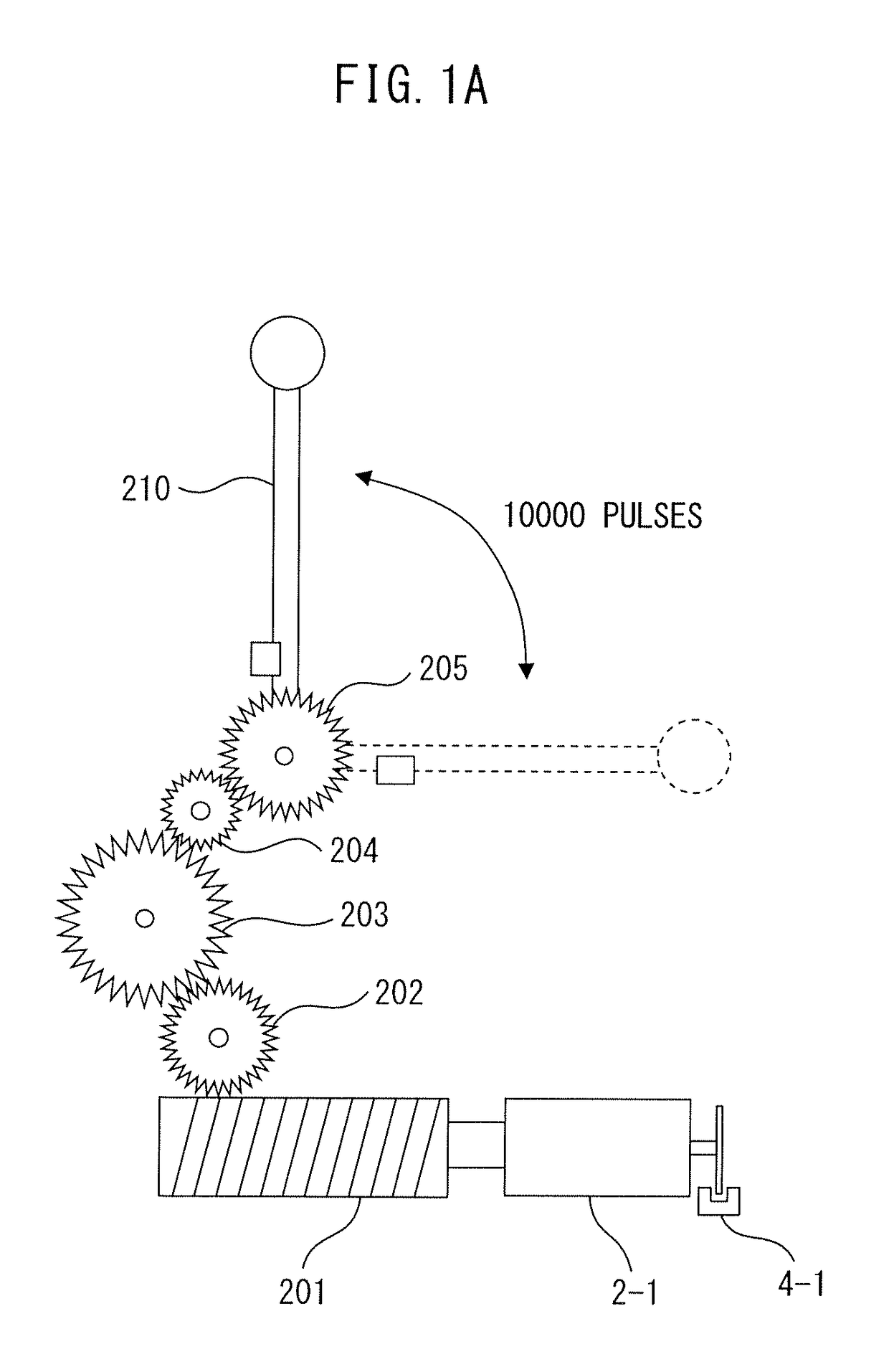
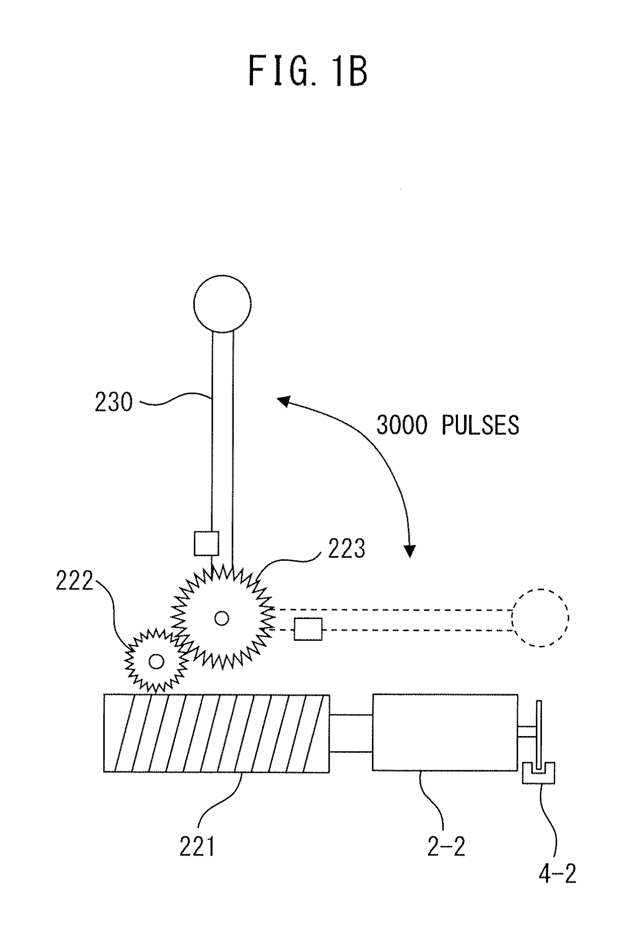
However, the space on the backside of the game machine is limited, and therefore as the number of motors increases, it may be difficult to arrange the motors in the game machine.
In particular, since the stepping motor needs to perform excitation control of a plurality of phases, the structure of the stepping motor is complicated, and the size of the stepping motor is correspondingly increased.
In addition, the stepping motor is relatively expensive.
Therefore, it is undesirable to increase the number of stepping motors.
However, in order to increase the torque of the stepping motor, there is no choice but to increase the size of the stepping motor itself, and as a result, it may become more difficult to secure an arrangement space.

Method used


Image

  • DC motor control device and game machine
  • DC motor control device and game machine
  • DC motor control device and game machine

Examples


first embodiment

[0039]FIG. 2 is a schematic block diagram of the DC motor control device according to the present invention. As illustrated in FIG. 2, the DC motor control device 1 includes a communication interface circuit 10, a communication circuit 11, two registers 12-1 and 12-2, two sensor interface circuits 13-1 and 13-2, two step counter circuits 14-1 and 14-2, two control circuits 15-1 and 15-2, and two drive signal generation circuits 16-1 and 16-2.

[0040]These units of the DC motor control device 1 may be mounted on a circuit board (not illustrated) as separate circuits, respectively, or may be mounted on the circuit board as an integrated circuit in which these units are integrated. Further, a register 12-1, a sensor interface circuit 13-1, a step counter circuit 14-1, a control circuit 15-1 and a drive signal generation circuit 16-1 are included in a drive unit 17-1, and are used for driving the DC motor 2-1. On the other hand, a register 12-2, a sensor interface circuit 13-2, a step cou...

second embodiment

[0104]Further, the sampling rate setting process is executed, so that the sampling rate to be used is registered in the sampling rate setting register 21 of the step counter circuit 14-1. Therefore, in the control command including the operation information, the sampling information may be omitted.

[0105]According to a modified example of each of the abovementioned embodiments, the control circuit may decrease the set sampling rate, when the difference between the target rotation amount specified by the control command and the number of steps from the start of movement of the movable body becomes equal to or less than a certain threshold value (for example, 100). For example, when the set sampling rate is (1 / n), the control circuit may set the sampling rate to (1 / (n / 2)) or 1. Thus, when the movable body approaches the movement destination, the control circuit can more precisely control the rotation amount of the DC motor.

[0106]According to another modified example, the control comma...


PUM


Abstract

A DC motor control device includes a communication circuit configured to receive a control command specifying a target rotation amount for a DC motor, a sensor interface configured to receive a detection signal from a rotational angle sensor that outputs the detection signal every time the DC motor rotates by a certain rotational angle, a step counter that outputs a count signal every time the detection signal has been received a certain number of times, a controller that, based on the number of times the count signal received, determines a step count representing the total amount of rotation, and generates a control signal that controls the DC motor in accordance with the step count and the target rotation amount, and a drive signal generation circuit that generates a drive signal that rotates the DC motor in accordance with the control signal.

Description

BACKGROUND[0001]Technical Field[0002]The present invention relates to a DC motor control device for controlling a DC motor and a game machine including such a DC motor control device.[0003]Related Art[0004]In a game machine such as a slot machine or a pinball machine, there are various ways to appeal to a visual sense, auditory sense, or a sensation of a player in order to enhance the interest of the player. In particular, in order to appeal to the visual sense of the player, the game machine may include a movable body, for example, a movable accessory member. A moving range and a moving speed of such a movable body are previously set depending on the performance. Therefore, generally, the movable body is driven by a stepping motor which has an already determined rotation amount per one step, and can control the rotation amount. Then, a processor unit for performance (simply referred to as performance CPU hereafter) which is an example of a host control device, transmits a command t...

Claims


Application Information

Patent Timeline
IPC IPC(8): H02P7/298A63F7/02
CPCH02P7/2985H02P8/00A63F7/02H02P7/29A63F7/022G07F17/3213H02P7/285
Inventor MATSUSHITA, KATSUMIIBUKI, HIROYUKI
Owner ORMON CORP
Learn More