
Foundation container comprising pump having convenient pressurization

a technology of a foundation container and a pump, which is applied in the field of foundation containers, can solve the problems of weak stability of the liquid foundation, inconvenient use, inconvenient use, etc., and achieve the effects of convenient pressurization, convenient pressurization, and convenient folding during pumping

Active Publication Date: 2017-10-05
KANG SUNGIL
View PDF28 Cites 10 Cited by
  • Summary
  • Abstract
  • Description
  • Claims
  • Application Information

AI Technical Summary

Benefits of technology

The present invention provides a foundation container with a pump that is convenient and easy to pressurize. The pump's outer wall is shaped like a concave janggu, allowing for even distribution of pressure across the pump's upper body. The pump is also conveniently folded during assembly, improving mass production efficiency. The pump's simplified structure reduces manufacturing costs and simplifies maintenance. Additionally, the foundation container includes a pump that prevents contamination from air, keeping the contents clean and sanitary for extended use.

Problems solved by technology

Although the solid foundation produces an effect of excellently covering the skin, the solid foundation may be conglomerated when correcting the makeup, and although the liquid foundation gives a good close contact feel, the persistency of the liquid foundation is weak.
However, according to the related art, the cosmetic contents are put on the hand whenever the user uses the gel foundation, so that it may be inconvenient for use.
Thus, in order to perform the pumping, the user needs to vertically pressurize a center portion of the impregnation member 180 by using the puff, so that it may be inconvenient for use.
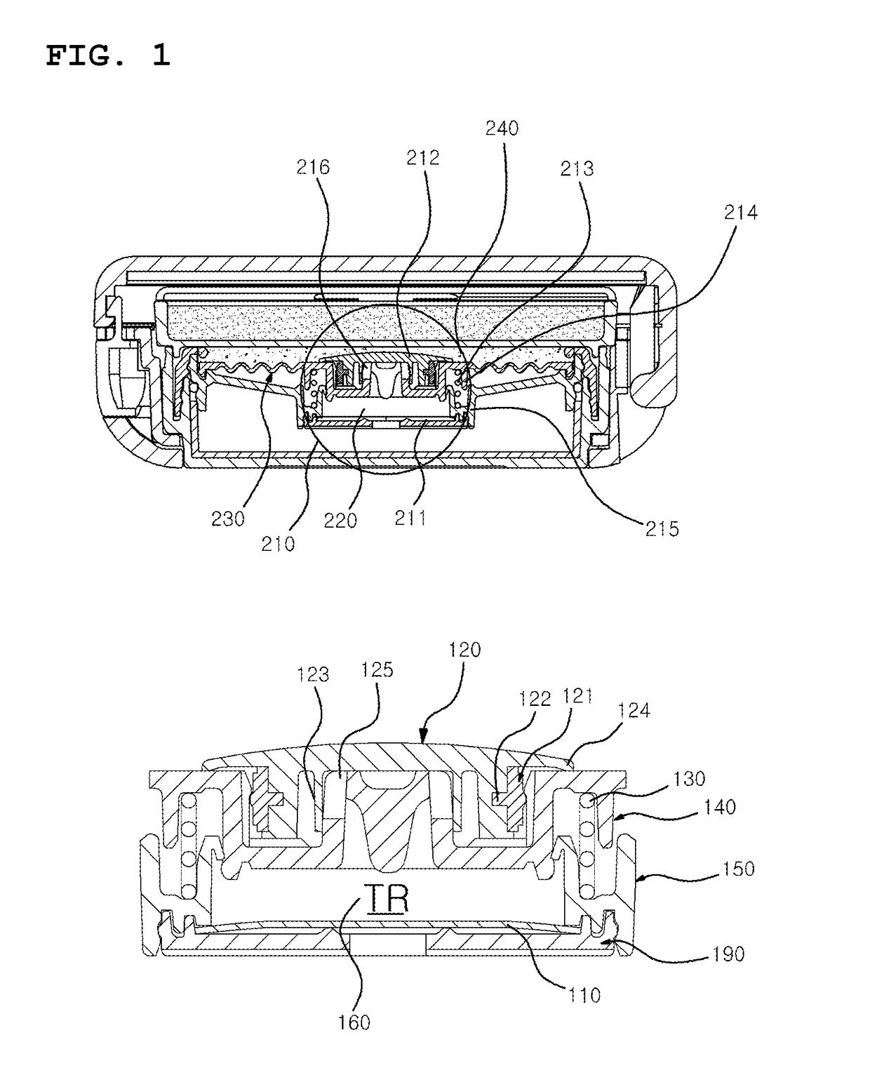
However, in order to assemble the pump, there are provided a coupling assistance member 121 for allowing the discharge valve 120 to be assembled onto the pump upper body 140, and a plurality of coupling annular protrusions and coupling grooves including a coupling annular protrusion 122, a valve annular protrusion 123, a sealing annular protrusion 124, an extension annular protrusion 124 and the like, so that the structure is not effectively simplified, and thus the number of assembling steps is increased, lowering the productivity.

Method used


Image

  • Foundation container comprising pump having convenient pressurization
  • Foundation container comprising pump having convenient pressurization
  • Foundation container comprising pump having convenient pressurization

Examples


first embodiment

[0056]A foundation container including a pump having convenient pressurization according to the present invention will be described with reference to accompanying drawings.

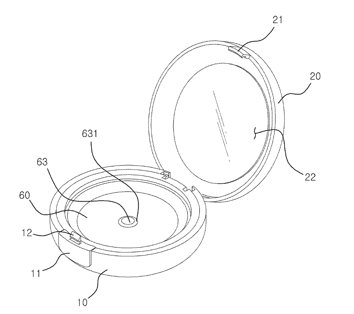
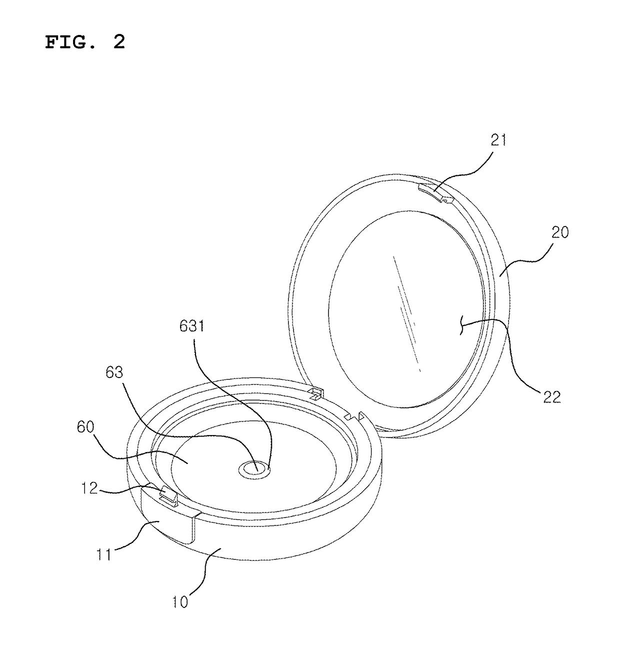
[0057]FIG. 2 is a perspective view showing a foundation container including a pump having convenient pressurization according to a first embodiment of the present invention, and FIG. 3 is an exploded perspective view showing the foundation container including the pump having convenient pressurization according to the first embodiment of the present invention. FIG. 4 is a sectional view showing the foundation container including the pump having convenient pressurization according to the first embodiment of the present invention, and FIG. 5 is a sectional view showing the foundation container including the pump having convenient pressurization in a state that a pump upper body of the foundation container is pressurized according to the first embodiment of the present invention. FIG. 6 is a sectional view showing the...

fourth embodiment

[0071]When storing the contents in the auxiliary container 34, as shown in FIG. 10, there may be further provided an impregnation member 80 provided inside the auxiliary container 34 and formed of porous foamed urethane according to the present invention.

[0072]The auxiliary container 34 is latched to the inner container body inner wall 31 of the inner container body 30.

[0073]The pump lower plate 40 is coupled to the upper portion of the inner container body 30 to seal the inner container body 30.

[0074]The pump lower plate 40 is preferably formed of at least one of elastic synthetic resin materials such as polyethylene (PE) or polypropylene (PP).

[0075]The pump lower plate 40 laterally extends to cover upper portions of the inner container body 30 and the auxiliary container 34, has a pump lower plate inner wall 41 and a pump lower plate outer wall 42 extending downwards, and is formed at the center thereof with the suction hole 45.

[0076]The pump lower plate inner wall 41 is fitted in...

second embodiment

[0095]In addition, according to the present invention as shown in FIG. 7, a center portion of the outer wall of the pump main body 50 outwardly protrudes in a shape of “”.

[0096]The pump upper body 60 is formed integrally with the upper portion of the pump main body 50, extends laterally, has the side wall 61 formed downwards from the pump upper body 60, and has the second latching protrusion 611 formed at an inner side of the side wall 61.

[0097]The pump upper body 60 is preferably formed of at least one of the elastic synthetic resin materials such as polyethylene (PE) or polypropylene (PP).

[0098]In addition, the pump upper body 60 may be formed separately from and coupled to the upper portion of the pump main body 50 to achieve a sealed state.

[0099]The present invention will be described based on a structure in which the pump upper body 60 is formed integrally with the pump main body 50.

[0100]The pump upper body 60 is formed integrally with the pump main body 50, so that the struct...


PUM


Abstract

The present invention relates to a foundation container comprising a pump having convenient pressurization and, more specifically, to a foundation container comprising a pump having convenient pressurization, wherein the outer wall of a pump main body is formed in the shape of an inwardly concave janggu (a Korean traditional hourglass drum), thereby not delimiting a pumping method to vertically pressurizing the center of a pump upper body, but facilitating the discharge of the contents even though any region of the pump upper body is pressurized. In addition, the present invention relates to a foundation container comprising a pump having convenient pressurization, wherein productivity is improved due to easy mass production by integrating a pump upper body and a pump main body in one body and forming a discharge valve and a suction valve in the same shape so as to simplify the structure of a pump.

Description

CROSS-REFERENCE TO RELATED APPLICATION[0001]This application claims the benefit of Korean application No. 20-2014-0006586, filed on Sep. 5, 2014 with the Korean Intellectual Property Office, the disclosure of which is incorporated herein by reference.TECHNICAL FIELD[0002]The present invention relates to a foundation container including a pump having convenient pressurization and, more specifically, to a foundation container including a pump having convenient pressurization, wherein an outer wall of a pump main body is formed in the shape of an inwardly concave janggu (a Korean traditional hourglass drum), thereby not delimiting a pumping method to vertically pressurizing the center of a pump upper body, but facilitating the discharge of the contents even though any region of the pump upper body is pressurized.[0003]In addition, the present invention relates to a foundation container including a pump having convenient pressurization, wherein productivity is improved due to easy mass ...

Claims


Application Information

Patent Timeline
Patent Type & Authority Applications(United States)
IPC IPC(8): A45D40/00B05B11/00A45D34/00B65D43/16A45D40/22
CPCA45D40/0075B65D43/163A45D2040/223A45D34/00B05B11/3002A45D40/222A45D33/02A45D33/025A45D2200/056B05B1/14B05B11/007B05B11/0072B05B11/026B05B11/028B05B11/1033B05B11/1069B05B11/1074A45D34/04B05B11/00B05B11/1002
Inventor KANG, SUNGIL
Owner KANG SUNGIL
Learn More