
Modular total knee arthroplasty system and method

a total knee arthroplasty and module technology, applied in the field of knee replacement surgery system and method, can solve the problems of complex and time-consuming, previously implanted knee prosthetic devices may loosen, revision surgery is typically more complicated and time-consuming, etc., and achieves the effect of less time-consuming and simplified delivery process

Active Publication Date: 2017-10-05
ARTHROLOGY CONSULTING LLC
View PDF2 Cites 0 Cited by
  • Summary
  • Abstract
  • Description
  • Claims
  • Application Information

AI Technical Summary

Benefits of technology

The invention provides an improved system and method for delivering and replacing knee replacement implants that simplifies the process and reduces the time required for the procedure. The system includes a modular trial implant assembly with an elongate shaft and a removable reamer that can be rotated while maintaining stability. The reamer has milling elements that form a tapered cavity in the bone. The system also includes a trial implant that can be coupled to the reamer for replacement. The elongate shaft provides angular orientation but not rotational stability, while the reamer provides rotational and axial stability in the tapered cavity. Overall, the system simplifies the process of delivering and replacing knee replacement implants.

Problems solved by technology

Such surgical procedures involve cutting sections of the femur and tibia to accommodate the prosthetic devices in proper alignment, and can be complex and time consuming.
For example, the previously implanted knee prosthetic devices may loosen over time, for example, from the production of wear debris, infection, or fracture.
Revision surgery is typically more complicated and time consuming than an initial knee replacement surgery because the surgeon must remove the previously implanted device, which was cemented into the bone or has existing bone into the device.

Method used


Image

  • Modular total knee arthroplasty system and method
  • Modular total knee arthroplasty system and method
  • Modular total knee arthroplasty system and method

Examples


Embodiment Construction

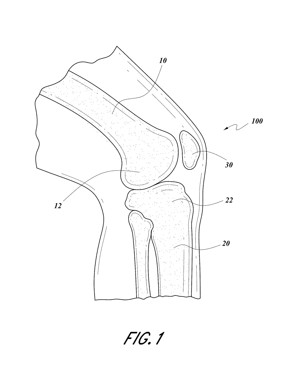
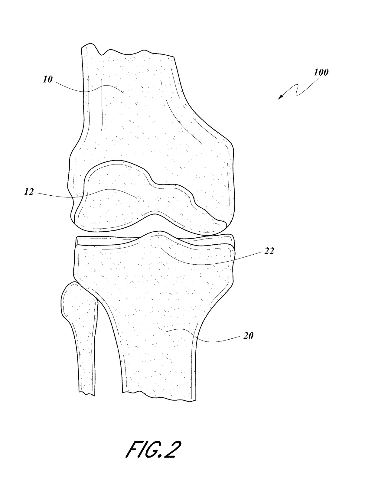
[0031]FIGS. 1-2 shows a schematic side and front view, respectively of a human knee joint 100, which includes a distal end 12 of a femur 10, a proximal end 22 of a tibia 20, and a patella 30. Total knee arthroplasty (TKA) involves removal of at least a portion of the distal end 12 of the femur 10 and at least a portion of the proximal end 22 of the tibia 20 and implantation of prosthetic femoral and tibial components, as described further below.

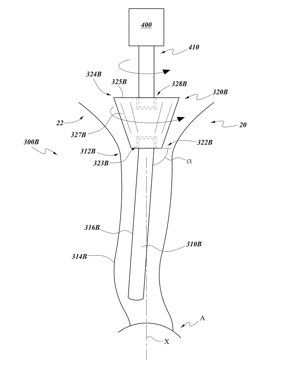
[0032]FIG. 3 shows one embodiment of an assembly 300 that can be used during a total knee replacement or total knee revision surgical procedure, as further discussed below. The assembly 300 can include an elongate shaft or stem 310 that can be inserted into the bone. In the illustrated embodiment, the assembly 300 is schematically shown disposed in the tibia 20. However, the assembly 300 can also be used in femur 10. The elongate shaft 310 extends between a proximal end 312 and a distal end 314 and has an outer surface 316. Optionally, the el...


PUM


Abstract

A modular system for total knee arthroplasty includes a modular trial implant assembly. The modular implant assembly includes an elongate shaft configured for insertion into an elongate cavity in a bone, a reamer removably coupleable to the elongate shaft via a connection that allows the reamer to rotate while the elongate shaft remains in a substantially fixed angular orientation. The reamer has an outer surface that tapers toward the distal end configured to form a tapered cavity in an end of a bone in which the reamer is inserted and rotated. The modular trial implant assembly further includes a trial implant removably coupleable to a proximal end of the reamer. A modular final implant assembly includes an elongate stem, a tapered body and an implant body, each having a size and shape that can substantially correspond to a size and shape of the elongate shaft, the reamer and the trial implant, respectively.

Description

CROSS-REFERENCE TO RELATED APPLICATIONS[0001]Any and all applications for which a foreign or domestic priority claim is identified in the Application Data Sheet as filed with the present application are hereby incorporated by reference under 37 CFR 1.57 and should be considered a part of this specification.BACKGROUNDField[0002]The present invention relates to a system and method for knee replacement surgery and more particularly to a modular total knee arthroplasty system and method for use in primary and revision knee replacement.Description of the Related Art[0003]Total or partial knee replacement is very common, for example to treat conditions such as arthritis or treat injuries to the knee joint (e.g., from trauma, accidents, sport injuries, etc.). Total knee arthroplasty involves implanting a first prosthetic device on the distal end of the femur and a second prosthetic device on the proximal end of the tibia, where the first and second prosthetic devices replace the natural ar...

Claims


Application Information

Patent Timeline
Patent Type & Authority Applications(United States)
IPC IPC(8): A61B17/16A61B17/17A61F2/46A61F2/38
CPCA61B17/1675A61F2/3859A61F2/4684A61B17/1764A61F2/389A61F2/461A61F2002/30205A61F2002/30616A61F2002/30878A61F2002/4619
Inventor AMANATULLAH, DEREK
Owner ARTHROLOGY CONSULTING LLC
Learn More