
Flame and particulate resistant knit article

a technology of particulate and knitted objects, which is applied in the direction of knitting, chemical protection, transportation and packaging, etc., can solve the problems of destroying the lightweight nanoweb, not fully understanding or appreciated, and the health threat posed by the deposition of particulate on the skin of smoke,

Active Publication Date: 2017-10-05
DUPONT SAFETY & CONSTR INC
View PDF9 Cites 2 Cited by
  • Summary
  • Abstract
  • Description
  • Claims
  • Application Information

AI Technical Summary

Benefits of technology

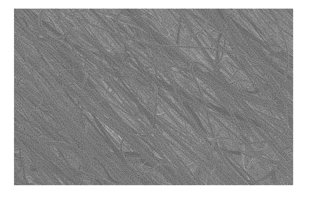
The invention is a protective clothing made of a durable multilayer fabric that includes flame-resistant layers. The fabric is made up of a first flame-resistant knitted fabric with a high fabric modulus, a flame-resistant nonwoven fabric with continuous filaments, and a second flame-resistant knitted fabric with a high fabric modulus. The nonwoven fabric is attached to both the first and second flame-resistant knitted fabrics at different attachment points, creating two unattached areas with a specific size. The value of both attachment points is calculated, and the value of the unattached areas is determined based on the average fabric modulus of the flame-resistant fabrics. The technical effect of this invention is a protective clothing that has excellent flame resistance and is made of a durable multilayer fabric that can withstand high levels of heat and fire.

Problems solved by technology

Further, it has been recognized that smoke from flames is an inhalation threat for fire fighters.
However, until recently the health threat posed by the deposition on the skin of particulates, such as the soot and other atomized particles in smoke, has not been fully understood or appreciated.
Again, until recently it was not fully recognized that clothing articles such as these were a “weak link” in preventing hazardous particle ingression and deposition on the skin.
Heretofore it has been thought that such movement is undesirable, because one would expect that any localized movement, with its associated layer-to-layer friction between the surfaces of the nanoweb and the surfaces of the outer fabrics, would simply destroy the lightweight nanoweb.
Further, if given a choice, such face-to-face bonded laminates would generally not be desirable for such as neck coverings including cowls, head coverings including hoods, collars, and related articles, because such laminates do not allow the fabrics to independently move and slide upon each other.

Method used


Image

  • Flame and particulate resistant knit article
  • Flame and particulate resistant knit article

Examples


example 1

[0053]Several precursor nonwoven sheets for forming nonwoven fabrics N1 to N7, were made by electroblowing a polyamic acid (PAA) solution comprising pyromellitic dianhydride (PMDA), oxy-dianiline (ODA) and dimethylformamide (DMF) into precursor nonwoven sheets of generally continuous polymer precursor filaments a manner similar to the process described in U.S. Pat. No. 7,618,579 and U.S. Pat. App. Pub. No. 2011 / 0144297. The precursor sheets were then further treated in a horizontal infrared oven without web restriction in the cross web direction as follows.

[0054]Highly elastic nonwoven fabric N1 was made by consecutive stretching and imidization of a precursor nonwoven sheet in accordance with the disclosure of United States Patent Appl. Pub. No. US2015 / 109063 to Simmonds et al. In this process, the precursor sheet was drawn to align and orient the filaments in the machine direction, and the drawn precursor sheet was then exposed to heat to complete the heat setting (i.e., imidizati...

example 2

[0063]Select durable to laundry laminates from Example 1 were subjected to the filtration efficiency testing using salt (NaCl) particles in a range of 0.1-0.8 micrometers and face velocities of 0.4 cm / s. The filtration efficiency results for 0.3 micrometer particles are presented in the Table 4. It is clear that the laminates maintain very good particle filtration efficiency after 20 washing cycles.

TABLE 4FiltrationFiltrationEfficiency,Efficiency,BeforeAfter 20Side 1Side 2NonwovenWashing,Cycles,LaminateknitknitFabric(%)(%)1-222N399.999.81-434N399.198.91-744N49995.81-844N598.987


PUM

PropertyMeasurementUnit
diameteraaaaaaaaaa
durableaaaaaaaaaa
modulusaaaaaaaaaa

Abstract

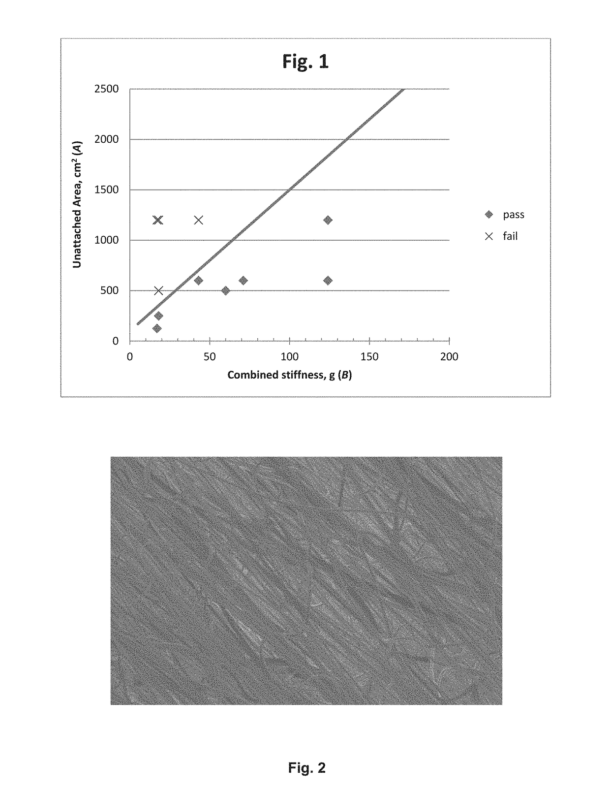
An article of protective clothing comprising a durable multilayer fabric laminate formed fromi) a first flame resistant knitted fabric made from yarns, the fabric having an average fabric modulus of 8 grams-force of greater;ii) a flame-resistant nonwoven fabric having a machine direction and a cross direction, and consisting of a plurality of continuous filaments having a diameter of less than 1000 nm, the filaments in the fabric being substantially oriented parallel with the machine direction and having stretch and recovery in the cross direction; andiii) a second flame resistant knitted fabric made from yarns, the fabric having an average fabric modulus of 8 grams-force of greater;wherein the nonwoven fabric is positioned between and coextensive with the first and second flame-resistant knitted fabrics; the nonwoven fabric being attached to the first knitted fabric by a set of first attachment points, the attachment points defining a first unattached area having a first effective diameter; the nonwoven fabric also being attached to the second knitted fabric by a set of second attachment points, the attachment points defining a second unattached area having a second effective diameter; wherein both the first unattached area and the second unattached area each have a value A, in square centimeters, according to the formula:C<A< / =(14*B)+100the value B being the sum of the average fabric modulus of the first knitted fabric and the average fabric modulus of the second knitted fabric, in grams-force; and the value C being 5 square centimeters.

Description

BACKGROUND OF THE INVENTIONField of the Invention[0001]This invention concerns an article of protective clothing that is both flame resistant and resistant to the ingression of particles.Background of the Invention[0002]Improvements in flame resistant protective apparel such as that designed for fire fighters has generally been directed at improved flame, thermal, or comfort performance. Further, it has been recognized that smoke from flames is an inhalation threat for fire fighters. However, until recently the health threat posed by the deposition on the skin of particulates, such as the soot and other atomized particles in smoke, has not been fully understood or appreciated.[0003]Fire-fighting turnout gear having multiple and thick layers of various materials by their nature provide some protection from the ingress of particles. However, any number of other pieces of protective gear such as neck coverings including such things as cowls, head coverings including such things as hood...

Claims


Application Information

Patent Timeline
Patent Type & Authority Applications(United States)
IPC IPC(8): A62B17/00A62B17/04A41D31/00A41D13/05
CPCA62B17/003A41D13/05A41D2500/10A62B17/04A41D31/0027A41D13/0512B32B5/26D04B1/16A41D31/085D04H13/00B32B5/279B32B7/09B32B7/05B32B37/144B32B5/06
Inventor LEVIT, NATALIA V.
Owner DUPONT SAFETY & CONSTR INC
Learn More