Oxide superconducting wire

Active Publication Date: 2017-10-05
FUJIKURA LTD
View PDF0 Cites 3 Cited by
  • Summary
  • Abstract
  • Description
  • Claims
  • Application Information

AI Technical Summary

Benefits of technology

The invention provides an oxide superconducting wire with a metal layer that can function as a bypass to limit the adverse influence of defects and prevent quenches. The metal layer also complemented a decrease in mechanical strength of the base material and increased the mechanical strength of the wire. Furthermore, the metal layer prevented the oxide superconducting layer from being exposed and deteriorating due to moisture from the outside. In addition, the metal layer enhanced the current-bypassing function and reliably prevented quenches even in the case of divided filaments.

Problems solved by technology

The shielding currents cause magnetization losses that are discharged in a heat form.
Therefore, when large shielding currents are generated, there has been a problem in that the energy efficiency of oxide superconducting wires decreases.
In addition, when an oxide superconducting wire is processed into a coil shape and is supplied with currents so as to generate a magnetic field, the magnetic field is shielded due to shielding currents, and there has been a problem in that the magnetic field cannot be generated as designed.
In addition, shielding currents attenuate over time.
Therefore, in a case in which an oxide superconducting wire is applied to a superconducting device generating a magnetostatic field which does not change over time, there has been a problem in that magnetic fields change over time due to the attenuation of shielding currents.

Method used


Image

  • Oxide superconducting wire
  • Oxide superconducting wire
  • Oxide superconducting wire

Examples


first embodiment

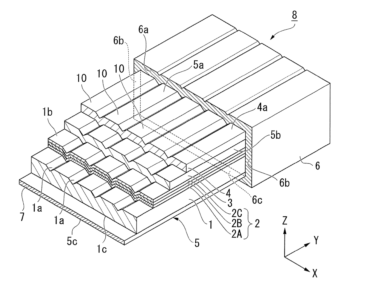
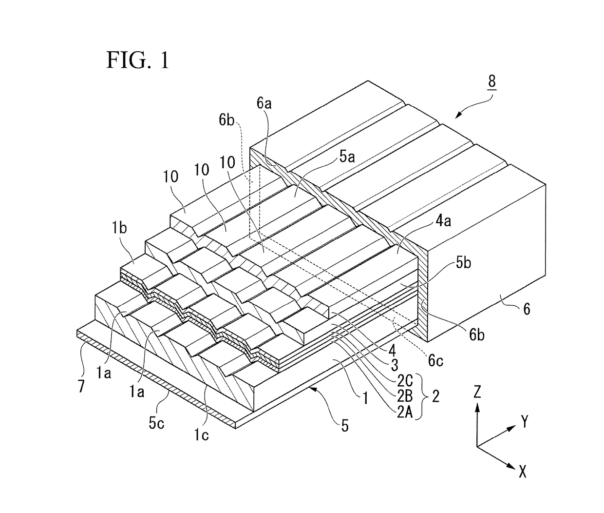
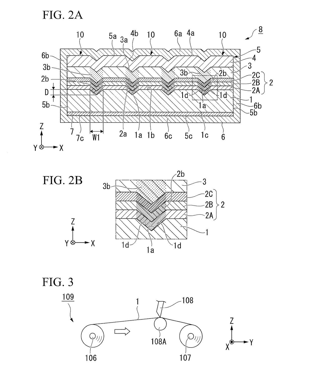
[0047]FIG. 1 shows a sectional perspective view of an oxide superconducting wire 8 according to the present embodiment. FIG. 2A shows a horizontal sectional schematic view of the oxide superconducting wire 8 according to the present embodiment. FIG. 2B shows a sectional enlarged view of the oxide superconducting wire 8 according to the present embodiment.

[0048]As shown in FIGS. 1, 2A, and 2B, the oxide superconducting wire 8 according to the present embodiment has a laminate 5 and a metal layer 6 formed at the outer circumference of the laminate 5.

[0049]The laminate 5 is constituted by laminating an intermediate layer 2, an oxide superconducting layer 3, and a metal-stabilizing layer 4 (first metal-stabilizing layer) in this order on a main surface 1b (first surface) of a base material 1 and forming a foundation layer (base material foundation layer) 7 on a rear surface 1c (second surface) of the base material 1. In other words, in the laminate 5, the base material 1 is formed on th...

modification example of first embodiment

[0132]FIGS. 4A and 4B show sectional views of an oxide superconducting wire 18 which is a modification example of the oxide superconducting wire 8 according to the first embodiment.

[0133]The oxide superconducting wire 18 is different from the oxide superconducting wire 8 shown in FIG. 1 in terms of the use of a metal layer 16 constituted of metal tape instead of the metal layer 6 formed by means of plating. Hereinafter, the same constitution as in the oxide superconducting wire 8 according to the first embodiment will be given the same reference number and will not be described.

[0134]The metal layer 16 is formed so as to cover at least the main surface 5a and the side surface 5b of the laminate 5.

[0135]In detail, as shown in FIG. 4B, the metal layer 16 has a main surface portion 16a, side surface portions 16b and 16b, and a rear surface portion 16c. The main surface portion 16a is provided on the main surface 4a side of the metal-stabilizing layer 4 and covers the main surface 4a. T...

second embodiment

[0144]Next, a second embodiment will be described.

[0145]FIG. 5A shows a sectional view of an oxide superconducting wire 28 according to the second embodiment. In addition, FIG. 5B is an enlarged view of a non-orientation region 33b in an oxide superconducting layer 33. Hereinafter, the oxide superconducting wire 28 will be described on the basis of FIGS. 5A and 5B.

[0146]The oxide superconducting wire 28 according to the second embodiment is different from the oxide superconducting wire 8 according to the first embodiment in terms of the constitution of a recessed groove portion 32Ba. Hereinafter, the same constitution as in the oxide superconducting wires 8 and 18 which are the first embodiment and the modification example of the first embodiment will be given the same reference number and will not be described.

[0147]As shown in FIGS. 5A and 5B, the oxide superconducting wire 28 includes a laminate 15 and the metal layer 6 formed on the outer circumference of the laminate 15.

[0148]T...


PUM

PropertyMeasurementUnit
Superconductivityaaaaaaaaaa
Crystal orientationaaaaaaaaaa

Abstract

An oxide superconducting wire, includes a laminate including a base material, an intermediate layer, and an oxide superconducting layer, the intermediate layer being laminated on a main surface of the base material, the intermediate layer being constituted of one or more layers having an orientation, the intermediate layer having one or more first non-orientation regions extending in a longitudinal direction of the base material, the oxide superconducting layer being laminated on the intermediate layer, the oxide superconducting layer having a crystal orientation controlled by the intermediate layer, the oxide superconducting layer having second non-orientation regions located on the first non-orientation regions, and a metal layer which covers at least a front surface and side surfaces of the oxide superconducting layer in the laminate.

Description

TECHNICAL FIELD[0001]The present invention relates to an oxide superconducting wire.[0002]Priority is claimed on Japanese Patent Application No. 2015-218911, filed Nov. 6, 2015, the content of which is incorporated herein by reference.BACKGROUND ART[0003]RE-123-based oxide superconductors (REBa2Cu3O7-x: RE represents rare earth elements including Y) exhibit superconductivity at the temperature of liquid nitrogen and have low current losses and are thus extremely promising materials in a practical sense, and there is demand for RE-123-based oxide superconductors to be processed into wires and be used as conductors or electromagnetic coils for power supply and the like.[0004]As an example of the structure of RE-123-based oxide superconducting wires, oxide superconducting wires obtained by using a base material made of a metal having a high mechanical strength, forming an intermediate layer having a favorable crystal orientation on the surface of the base material using an ion-beam-ass...

Claims


Application Information

Patent Timeline
IPC IPC(8): H01B12/06C23C14/22C23C14/08H01F6/06C23C14/46C25D7/06C25D3/38C01G3/00C23C14/18
CPCH01B12/06C01G3/006C23C14/221C23C14/081C23C14/082C01P2006/40C23C14/46C25D7/0607C25D3/38H01F6/06C23C14/18H10N60/85C23C14/08H10N60/203H10N60/0632
Inventor KURIHARA, CHIHAYA
Owner FUJIKURA LTD
Why Eureka
Try Eureka