Device and method for manufacturing optical fibre coupling connector

A technology for optical fiber coupling and manufacturing devices, which is applied to the coupling of optical waveguides, optical components, and other household appliances, etc., can solve the problems of the mechanical strength drop of the substructure, and achieve the effect of reducing the drop in mechanical strength

Inactive Publication Date: 2011-10-12
HONG FU JIN PRECISION IND (SHENZHEN) CO LTD +1
View PDF2 Cites 0 Cited by
  • Summary
  • Abstract
  • Description
  • Claims
  • Application Information

AI Technical Summary

Problems solved by technology

[0004] In the injection molding process, if single-point pouring is used, the key points of the fiber optic coupling connector will be filled early, ...

Method used


Image

  • Device and method for manufacturing optical fibre coupling connector
  • Device and method for manufacturing optical fibre coupling connector
  • Device and method for manufacturing optical fibre coupling connector

Examples


Embodiment Construction

[0032] The present invention will be described in further detail below in conjunction with the accompanying drawings.

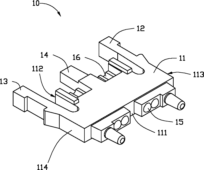
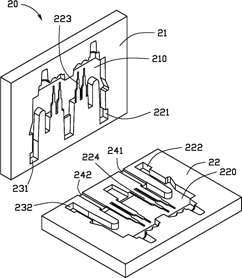
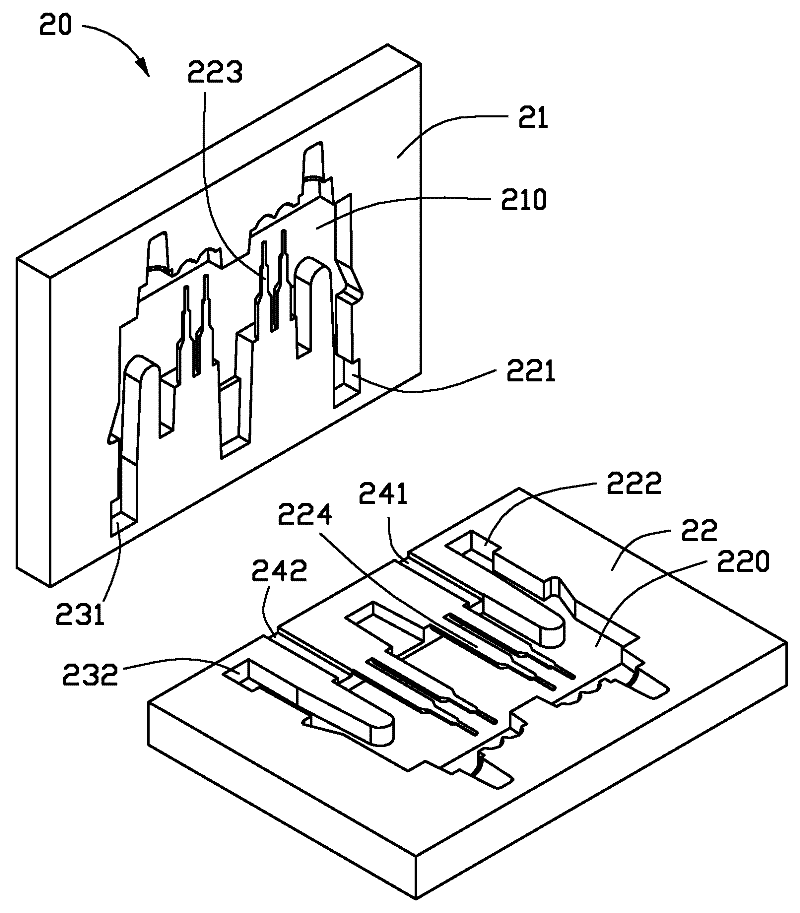
[0033] see figure 1 and figure 2 As shown, the optical fiber coupling connector manufacturing apparatus 20 of the embodiment of the present invention is used for injection molding the optical fiber coupling connector 10 .

[0034] The optical fiber coupling connector 10 has a body 11 and a first side wall 12 distributed at one end of the body 11, a second side wall 13, and a central portion 14 between the first side wall 12 and the second side wall 13, and the other end is provided with Lens 15. Between the first side wall 12 and the central part 14, between the second side wall 13 and the central part 14, there are respectively blind holes 16, the blind holes 16 are used to accommodate optical fibers, and the lens 15 is located at the bottom of the blind holes 16 to optically couple with the optical fibers .

[0035] The number of blind holes 16 is not ...


PUM


Abstract

A device for manufacturing an optical fibre coupling connector comprises a die cavity which is used for forming the optical fibre coupling connector. The optical fibre coupling connector is provided with a main body and a blind hole formed on the main body. A cavity insert for forming the blind hole is arranged in the die cavity. Besides, a first pouring gate and a second pouring gate are formed on the two sides of the cavity insert. The invention also relates to a method for manufacturing an optical fibre coupling connector.

Description

technical field [0001] The invention relates to a manufacturing device and a manufacturing method of an optical fiber coupling connector. Background technique [0002] Fast network transmission mainly uses fiber optics for signal transmission. If this fiber optic transmission principle can be applied to the USB (Universal Serial Bus) connector in the computer, the transmission speed will be improved. [0003] In USB transmission components, the key point is that optical components must be structurally assembled and matched with optical fibers. The diameter of common optical fibers is 0.126mm, so there is a high production bottleneck in the production of optical components. Fiber optical components are produced by injection molding. The key dimension of the finished product is the aperture of the fiber. The aperture is controlled by the outer diameter of the insert on the mold and matched with the injection molding parameters. [0004] In the injection molding process, if si...

Claims


Application Information

Patent Timeline
IPC IPC(8): B29C45/26G02B6/36B29L11/00
Inventor 林俊宇
Owner HONG FU JIN PRECISION IND (SHENZHEN) CO LTD
Why Eureka
Try Eureka