Self-generating power generation system

a power generation system and self-generating technology, applied in the direction of battery/fuel cell control arrangement, electric devices, propulsion by batteries/cells, etc., can solve the problems of difficult to give one single comprehensive definition of energy, the current method of production and the way that electricity is generally used far from the most effective use of resources for the technology that is now availabl

a power generation system and self-generating technology, applied in the direction of battery/fuel cell control arrangement, electric devices, propulsion by batteries/cells, etc., can solve the problems of difficult to give one single comprehensive definition of energy, the current method of production and the way that electricity is generally used far from the most effective use of resources for the technology that is now availabl

US20170288526A1Inactive Publication Date: 2017-10-05ALHERAIQI OMAR

Image

  • Self-generating power generation system
  • Self-generating power generation system
  • Self-generating power generation system

Examples


Embodiment Construction

[0022]As discussed above, embodiments of the present invention relate to a power generating system and more particularly to a self-generating power generation system as used to improve the efficiency of a power generating system by cogenerating power from the input power supply.

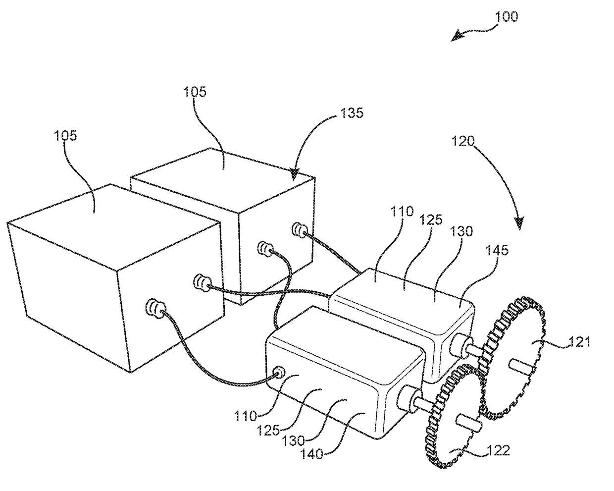
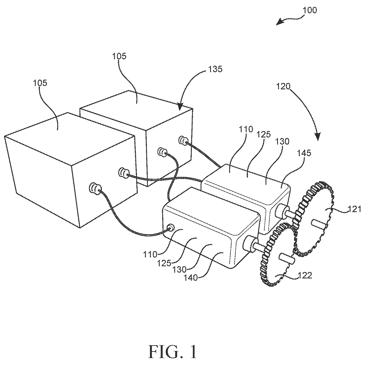
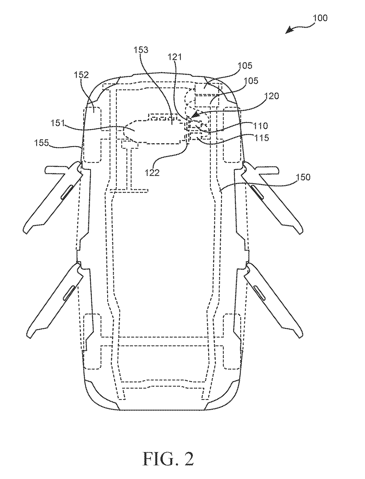
[0023]Generally speaking, a self-generating power generation system is a generating system that is designed to use a portion of the incoming power to generate additional power to make the system highly efficient. The system may be used in a motor vehicle and take advantage of the available kinetic energy of the turning wheels regenerate power to multiply the efficiency. The system uses two batteries, a brushless DC motor, a generator, gearing, relays, switches, a regulator, a diode, and a controller.

[0024]In greater detail now, referring to the drawings by numerals of reference there is shown in FIG. 1, a perspective view illustrating self-generating power generation system 100 according to an embodiment of t...


PUM


Abstract

A self-generating power generation system is a generating system that is designed to use a portion of the incoming power to generate additional power to make the system highly efficient. The system may be used in a motor vehicle and take advantage of the available kinetic energy of the turning wheels regenerate power to multiply the efficiency. The system uses two batteries, a brushless dc motor, a generator, gearing, relays, switches, a regulator, a diode, and a controller.

Description

CROSS-REFERENCE TO RELATED APPLICATION[0001]The present application is related to and claims priority from prior provisional application Ser. No. 62 / 315,558, filed Mar. 30, 2016 which application is incorporated herein by reference.COPYRIGHT NOTICE[0002]A portion of the disclosure of this patent document contains material which is subject to copyright protection. The copyright owner has no objection to the facsimile reproduction by anyone of the patent document or the patent disclosure, as it appears in the Patent and Trademark Office patent file or records, but otherwise reserves all copyright rights whatsoever. 37 CFR 1.71(d).BACKGROUND OF THE INVENTION[0003]The following includes information that may be useful in understanding the present invention(s). It is not an admission that any of the information provided herein is prior art, or material, to the presently described or claimed inventions, or that any publication or document that is specifically or implicitly referenced is pr...

Claims


Application Information

Patent Timeline
05 Oct 2017
Publication
US20170288526A1
IPC
H02K47/14; H02K7/116; H02K11/33; B60L11/18
CPC
H02K47/14; B60L11/1805; B60L11/1864; B60L11/1861; H02K7/116; Y10S74/09; B60L11/1809; B60K2001/0411
Inventors
ALHERAIQI, OMAR