Power detection and transmission circuit coupling analog input signal on primary side to secondary side for power information calculation and related power supply apparatus

a transmission circuit and input signal technology, applied in the field of power detection, can solve the problems of increasing circuit complexity and cost accordingly, increasing programming complexity, increasing power consumption, etc., and achieve the effects of reducing manufacturing costs, simplifying circuit design, and reducing programming complexity

Active Publication Date: 2017-10-05
SPI ELECTRONICS
View PDF3 Cites 1 Cited by
  • Summary
  • Abstract
  • Description
  • Claims
  • Application Information

AI Technical Summary

Benefits of technology

The proposed power detection and transmission structure aims to simplify circuit design and reduce manufacturing costs by calculating complete system power information without the need for a microcontroller installed on a primary side, a UART interface, and an extra sensing resistor. Therefore, this structure may not only reduce programming complexities but also achieve lower manufacturing costs.

Problems solved by technology

However, problems arise when a microcontroller is installed on a primary side to measure an input voltage / current signal.
For example, the microcontroller 120 needs an extra voltage regulator and an independent ground path, and has to utilize the extra sensing resistor RS externally disposed on the primary side of the power supply module 110 to measure the input current signal CT, which results in increased power consumption.
In addition, as the microcontroller 120 is installed on the primary side and therefore requires an ability to withstand high surge voltages, circuit complexity and cost increase accordingly.
Moreover, as the microcontroller 120 needs the UART interface to transmit the calculated data to the microcontroller 130, this increases programming complexity.

Method used


Image

  • Power detection and transmission circuit coupling analog input signal on primary side to secondary side for power information calculation and related power supply apparatus
  • Power detection and transmission circuit coupling analog input signal on primary side to secondary side for power information calculation and related power supply apparatus
  • Power detection and transmission circuit coupling analog input signal on primary side to secondary side for power information calculation and related power supply apparatus

Examples


Embodiment Construction

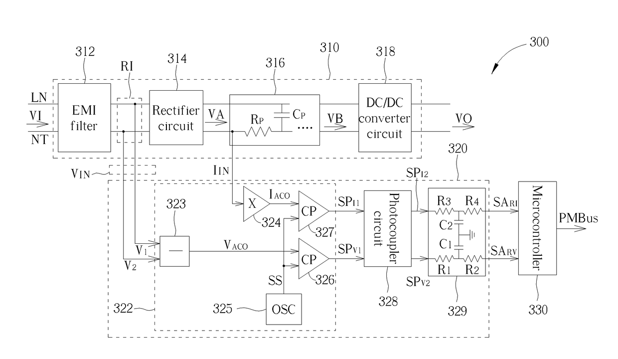
[0022]By converting an analog input signal on a primary side of a power supply module to a pulse width modulation (PWM) signal, and coupling the converted PWM signal to a microcontroller installed on a secondary side of the power supply module, the proposed power detection structure may calculate power information of the power supply module without the need for a microcontroller installed on the primary side of the power supply module. In other words, the proposed power detection and transmission structure may calculate complete system power information without the need for a UART interface and a microcontroller installed on the primary side.

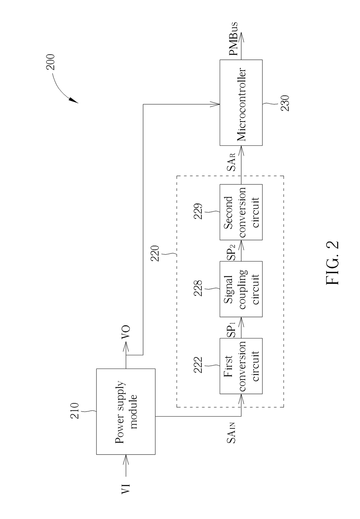
[0023]FIG. 2 is a block diagram illustrating an exemplary power supply apparatus according to an embodiment of the present invention. The power supply apparatus 200 may include, but is not limited to, a power supply module 210, a power detection and transmission circuit 220 and a microcontroller 230. The power supply module 210 may receive an in...


PUM


Abstract

A power detection and transmission circuit is provided. The power detection and transmission circuit includes a first conversion circuit, a second conversion circuit and a signal coupling circuit. The first conversion circuit is electrically connected to a power supply module to receive an analog input signal, and is arranged for converting the analog input signal to a first pulse width modulation (PWM) signal. The second conversion circuit is arranged for converting a second PWM signal to an analog regenerated signal, and transmitting the analog regenerated signal to a microcontroller, wherein the microcontroller calculates power information of the power supply module according to the analog regenerated signal. The signal coupling circuit is coupled between the first conversion circuit and the second conversion circuit, and is arranged for coupling the first PWM signal to the second conversion circuit and accordingly generating the second PWM signal.

Description

CROSS REFERENCE TO RELATED APPLICATIONS[0001]This application claims the benefit of U.S. provisional application No. 62 / 315,677, filed on Mar. 31, 2016, the contents of which are incorporated herein by reference.BACKGROUND OF THE INVENTION1. Field of the Invention[0002]The disclosed embodiments of the present invention relate to power detection, and more particularly, to a power detection and transmission circuit, which converts an analog input signal on a primary side of a power supply module and couples the resulting signal to a secondary side of the power supply module to thereby calculate power information of the power supply module at the secondary side, and a related power supply apparatus.2. Description of the Prior Art[0003]A conventional power supply apparatus needs a microcontroller, which is installed on a primary side of the conventional power supply apparatus, to measure an input voltage signal and an input current signal, and also needs a Universal Asynchronous Receive...

Claims


Application Information

Patent Timeline
Patent Type & Authority Applications(United States)
IPC IPC(8): H02M3/04G01R21/06H02M7/04G01R21/127H02M1/42H02M1/44
CPCH02M3/04H02M1/42G01R21/06H02M7/04G01R21/127H02M1/44G01R21/133
Inventor LIN, KUO-FANTU, FU-KAI
Owner SPI ELECTRONICS
Why Eureka
Try Eureka