Phosphor wheel, light source apparatus, and projection-type display apparatus

Active Publication Date: 2017-10-12
SONY CORP
View PDF2 Cites 39 Cited by
  • Summary
  • Abstract
  • Description
  • Claims
  • Application Information

AI Technical Summary

Benefits of technology

This patent describes how to create a phosphor wheel, light source, and projection-type display that can better manage heat dissipation without causing air resistance or noise. In simple terms, this patent helps to improve the cooling efficiency of the phosphor wheel.

Problems solved by technology

However, the heat dissipation unit described in Patent Literature 1 is composed of fins raised in a direction orthogonal to the substrate surface, and is likely to encounter air resistance during the rotation of the color wheel and cause large windage loss.
Therefore, in the color wheel described in Patent Literature 1, the power consumption of the motor that rotationally drives the color wheel may be increased.
Furthermore, in the color wheel described in Patent Literature 1, when the rotation rate is increased, the noise may be increased due to the air resistance encountered by the fins.

Method used


Image

  • Phosphor wheel, light source apparatus, and projection-type display apparatus
  • Phosphor wheel, light source apparatus, and projection-type display apparatus
  • Phosphor wheel, light source apparatus, and projection-type display apparatus

Examples


first embodiment

1. FIRST EMBODIMENT

1.1. EXAMPLE OF CONFIGURATION OF PROJECTION-TYPE DISPLAY APPARATUS

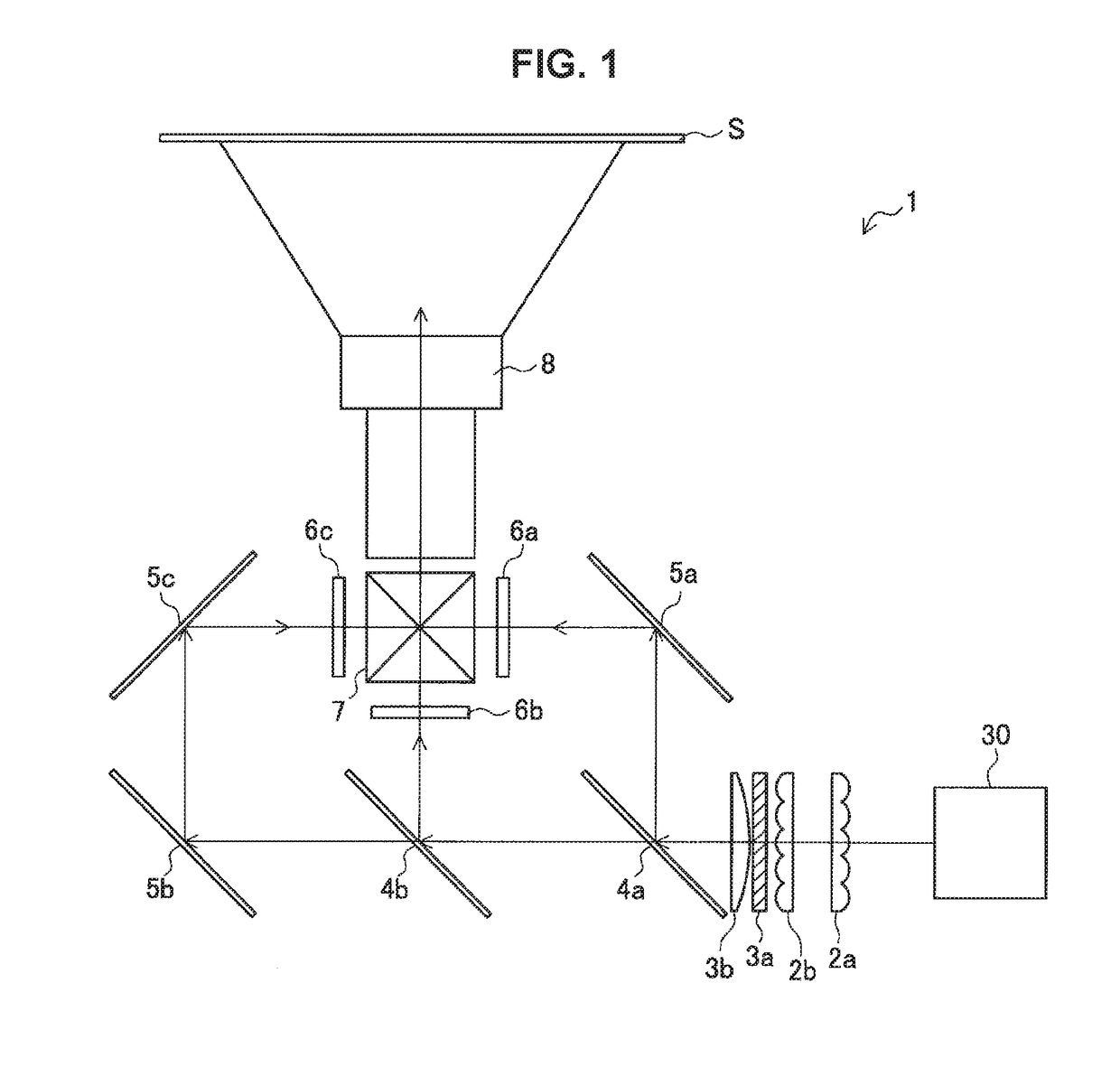
[0059]First, an example of the configuration of a projection-type display apparatus 1 including a light source apparatus 10 according to a first embodiment of the present disclosure is described with reference to FIG. 1. FIG. 1 is a diagram showing a rough configuration of the projection-type display apparatus 1 including the light source apparatus 10 according to this embodiment.

[0060]The projection-type display apparatus 1 according to this embodiment is a projector that condenses the light emitted from a light source, emits light from a projection lens through a device that causes an image to be displayed, and projects an image on a display surface such as a screen S. The projection-type display apparatus 1 shown in FIG. 1 is an example of the configuration of a projector using a 3LCD as a micro-display.

[0061]The light emitted from the light source apparatus 10 passes through integrator lenses 2 ...

modification examples

1.5. MODIFICATION EXAMPLES

[0099]Next, Modification Examples of the phosphor wheel 100 according to this embodiment are described.

modification example 1

1.5.1. Modification Example 1

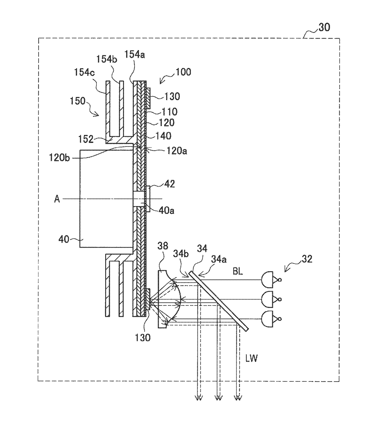
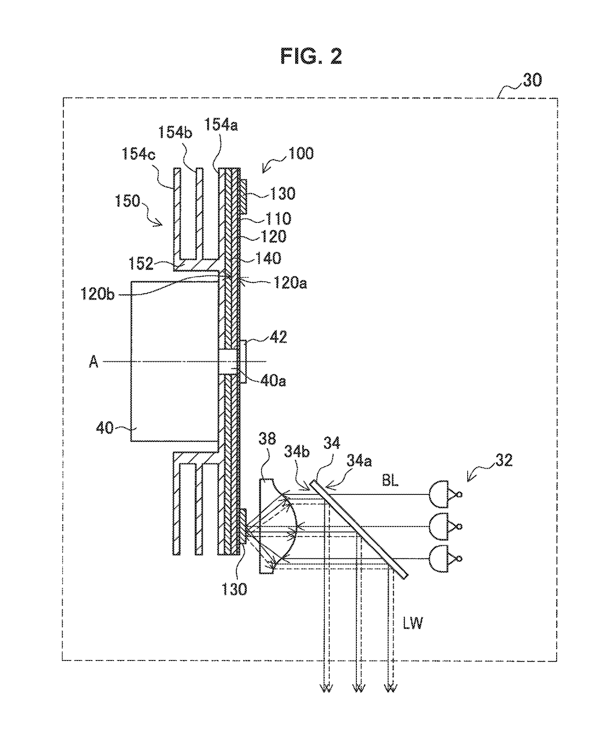
[0100]FIG. 6 shows Modification Example 1 of this embodiment. FIG. 6 shows a cross-sectional view of a phosphor wheel 100A according to Modification Example 1 taken along a plane including the rotation axis A. In the phosphor wheel 100A, the rising position of the rising section 152 of the heat dissipation structure unit 150 joined to the surface 120b of the substrate 120 corresponds to the position of formation of the phosphor layer 130. In the phosphor wheel 100A, the irradiation position of excitation light BL is set to a position satisfying the following relation.

D / 2R

[0101]R: the distance from the center of the substrate (the rotation axis A) to the irradiation position

[0102]D: the diameter of the rising portion of the rising section

[0103]The irradiation position of excitation light BL may be set to a position satisfying the above condition of D / 2<R and further satisfying the following relation.

0.4≦S / SA≦0.6

[0104]SA: the entire surface area of the ar...


PUM


Abstract

An object of the present invention is to improve the efficiency of heat dissipation from a phosphor wheel while suppressing the air resistance and noise of the phosphor wheel during the driving of a light source apparatus. A phosphor wheel (100) according to the present invention includes: a disc-like substrate (120); a phosphor layer (130) formed on the substrate; and a plurality of heat dissipation fins (154a, 154b, and 154c) overlapping with each other when viewed in a direction orthogonal to a surface of the substrate.

Description

TECHNICAL FIELD[0001]The present disclosure relates to a phosphor wheel, a light source apparatus, and a projection-type display apparatus.BACKGROUND ART[0002]As a light source used for a projection-type display apparatus such as a projector, an ultra-high pressure mercury vapor lamp is mainly used from the viewpoints of brightness and cost performance, but a solid state light source having a long lifetime and a wide color range is drawing attention from the viewpoints of long lifetime characteristics, high functionality addition, etc. The solid state light source is a light source using a light emission phenomenon based on a p-n junction of semiconductors, and is typified by an LED, a laser (LD), and the like. These days, a light source apparatus in which a solid state light source is used to apply light to a phosphor material that, when irradiated with light in a specific wavelength range, emits light in a wavelength range different from the wavelength range of the applied light a...

Claims


Application Information

Patent Timeline
IPC IPC(8): G03B21/16F21V14/08G03B33/12G02B26/00H04N9/31G03B21/20F21V29/76F21V9/16
CPCG03B21/16F21V29/76F21V14/08F21V9/16G02B26/008F21Y2115/30H04N9/3144G03B21/204G03B33/12G03B21/006H04N9/3161G03B21/00G03B21/14H04N9/3158G02B19/0014C09K11/7706F21V9/30
Inventor KOBAYASHI, IZUSHIISHIGE, MASAHIROMAEDA, YUKI
Owner SONY CORP
Why Eureka
Try Eureka