
Pitch reducing optical fiber array and multicore fiber comprising at least one chiral fiber grating

a chiral fiber and array technology, applied in the direction of optical fibers with polarisation, instruments, cladding optical fibres, etc., can solve the problems of increasing the coupling coefficient at each interface, significant challenges in interfacing dissimilarity, and increasing the insertion loss, so as to reduce the coupling of the first core mode

Active Publication Date: 2017-10-19
CHIRAL PHOTONICS
View PDF0 Cites 38 Cited by
  • Summary
  • Abstract
  • Description
  • Claims
  • Application Information

AI Technical Summary

Benefits of technology

The patent text describes innovative features in optical couplers for optical devices. These couplers use a common single coupler housing structure and a plurality of longitudinal waveguides that are positioned close to each other. The waveguides have a predetermined pitch and propagation constants that allow for the coupling of optical modes in a specific wavelength range. The couplers also include a chiral fiber grating that controls the coupling of light signals in a specific wavelength range. The technical effects of these features include improved coupling efficiency, reduced crosstalk, and improved mode control.

Problems solved by technology

However, there are significant challenges in interfacing dissimilar NA waveguide devices and multichannel devices with channel spacing less than a diameter of conventional fibers, with conventional optical fibers.
Failure to properly address these obstacles can result in increased insertion losses and a decreased coupling coefficient at each interface.
However, there are a number of disadvantages to this approach.
For example, a fiber cladding-capillary tube interface becomes a light guiding interface of a lower quality than interfaces inside standard optical fibers and, therefore, can be expected to introduce optical loss.
Furthermore, the capillary tube must be fabricated using a costly fluorine-doped material, greatly increasing the expense of the coupler.
Nevertheless, a number of challenges still remained.
With the proliferation of multichannel optical devices (e.g., waveguide arrays), establishing low-loss high-accuracy connections to arrays of low or high NA waveguides often was problematic, especially because the spacing between the waveguides is very small making coupling thereto all the more difficult.

Method used


Image

  • Pitch reducing optical fiber array and multicore fiber comprising at least one chiral fiber grating
  • Pitch reducing optical fiber array and multicore fiber comprising at least one chiral fiber grating
  • Pitch reducing optical fiber array and multicore fiber comprising at least one chiral fiber grating

Examples


Embodiment Construction

[0088]The chiral fiber grating (CFG) has been developed to address applications requiring wavelength selective control of the light in various types of single core fibers, as described in various patent applications referenced herein including U.S. Pat. No. 8,218,921, entitled “DUAL TWIST SINGLE HELIX OPTICAL FIBER GRATING,” filed Jul. 14, 2009; U.S. Pat. No. 7,463,800, entitled “CHIRAL FIBER GRATING DEVICE AND METHOD OF FABRICATION THEREOF,” filed Dec. 27, 2006; U.S. Pat. No. 7,142,280, entitled “EXTENDED CHIRAL DEFECT STRUCTURE APPARATUS AND METHOD,” filed Mar. 14, 2003; U.S. Pat. No. 7,095,911, entitled “CHIRAL IN-FIBER POLARIZER APPARATUS AND METHOD,” filed Oct. 25, 2004; U.S. Pat. No. 6,925,230 entitled “LONG PERIOD CHIRAL FIBER GRATING APPARATUS,” filed Mar. 21, 2003; U.S. Pat. No. 6,891,992, entitled “CONFIGURABLE ADD-DROP FILTER UTILIZING CHIRAL FIBER GRATINGS,” filed Apr. 12, 2002; U.S. Pat. No. 6,839,486, entitled “CHIRAL FIBER GRATING,” filed Mar. 14, 2002; U.S. Pat. No. ...


PUM


Abstract

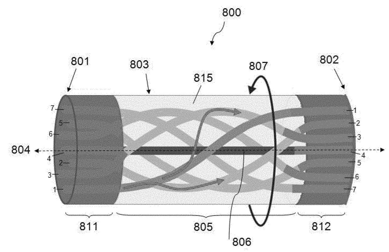
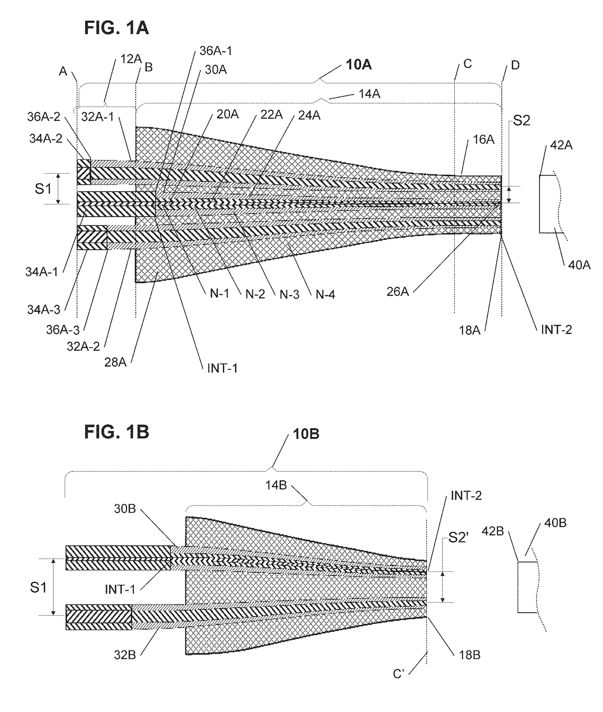
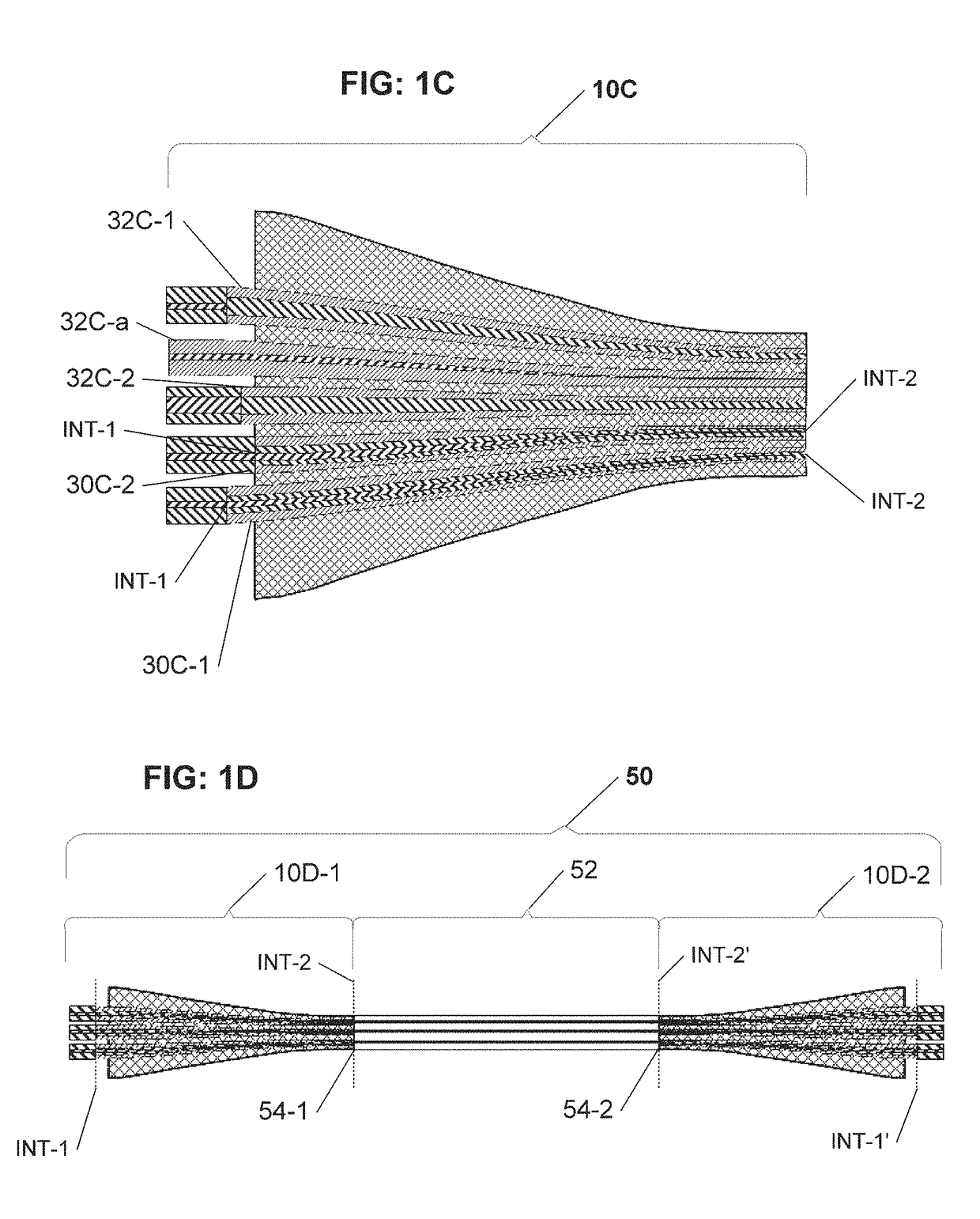
The present disclosure provides a pitch reducing optical fiber array or a multicore fiber including at least one chiral fiber grating incorporated therein that is operable to couple the modes in different fiber cores within a spectral range determined in some instances by the helical pitch of the corresponding chiral fiber grating.

Description

CROSS-REFERENCE TO RELATED APPLICATIONS[0001]This application claims the benefit of priority of U.S. Provisional Application No. 62 / 324,308, entitled “PITCH REDUCING OPTICAL FIBER ARRAY AND MULTICORE FIBER COMPRISING AT LEAST ONE CHIRAL FIBER GRATING,” filed Apr. 18, 2016, the entire disclosure of which is expressly incorporated herein by reference.[0002]This application also incorporates by reference the entirety of each of the following patent applications: U.S. Pat. No. 8,218,921, entitled “DUAL TWIST SINGLE HELIX OPTICAL FIBER GRATING,” filed Jul. 14, 2009; U.S. Pat. No. 7,463,800, entitled “CHIRAL FIBER GRATING DEVICE AND METHOD OF FABRICATION THEREOF,” filed Dec. 27, 2006; U.S. Pat. No. 7,142,280, entitled “EXTENDED CHIRAL DEFECT STRUCTURE APPARATUS AND METHOD,” filed Mar. 14, 2003; U.S. Pat. No. 7,095,911, entitled “CHIRAL IN-FIBER POLARIZER APPARATUS AND METHOD,” filed Oct. 25, 2004; U.S. Pat. No. 6,925,230 entitled “LONG PERIOD CHIRAL FIBER GRATING APPARATUS,” filed Mar. 21...

Claims


Application Information

Patent Timeline
IPC IPC(8): G02B6/02
CPCG02B6/02042G02B6/02085G02B2006/0209G02B6/105G02B6/36G02B6/14G02B6/4413G02B6/4401G02B6/24G02B6/4403G02B6/024G02B6/4249
Inventor KOPP, VICTOR IL'ICH
Owner CHIRAL PHOTONICS
Learn More