
System and method for guided removal from an in vivo subject

a technology of in vivo objects and systems, applied in the direction of guide wires, infusion syringes, applications, etc., can solve the problems of affecting millions of individuals worldwide, affecting the health of individuals, and causing significant pain to individuals and kidneys

Inactive Publication Date: 2017-10-26
THE GENERAL HOSPITAL CORP
View PDF4 Cites 33 Cited by
  • Summary
  • Abstract
  • Description
  • Claims
  • Application Information

AI Technical Summary

Benefits of technology

The patent text describes methods for removing objects from a passageway in an in vivo subject, such as kidney stones or bladder stones. The methods involve inserting a guide wire, positioning a sheath over the guide wire, and then using a ureteroscope to break the object into fragments. The fragments are then removed using a multi-lumen catheter with a valve to apply suction. A stent may be placed in the passageway to keep it open. The methods may involve injecting an irrigation fluid and suction simultaneously or intermittently to remove debris. The technical effects of the patent text include providing safer and effective methods for removing objects from a passageway in a minimally invasive way.

Problems solved by technology

Kidney stones are a common medical problem that negatively impact millions of individuals worldwide.
Kidney stones range in size from smaller (less than about 1 cm) to very large (more than 4 cm) and may cause significant pain to the individual and damage to the kidney.
There are numerous drawbacks associated with nephrolithotomy, nephrolithotripsy, and other invasive surgeries requiring an incision in the skin.
Namely, such surgical techniques may require significantly more anesthesia administered to the patient, the surgeries are more complicated and pose a higher risk of infection and complications for the patient, and the surgeries require a substantial incision in the patient, which may leave a scar.
Additionally, given the invasiveness of the procedure, percutaneous procedures are usually not preferred for smaller kidney stones (e.g., less than 1 cm) depending on the size and location of the stones.
It should be apparent that this process is extremely time consuming, costly, and inefficient because the surgeon is required to insert and remove the scope and basket into and out of the patient many times to completely remove the kidney stones and kidney stone fragments therefrom.
Using a basket removal device to capture kidney stones or kidney stone fragments suffers from other drawbacks in that the basket is difficult to position adjacent the kidney stone fragments and maneuver in a manner that effectively retrieves the fragments.
The training required for such a procedure is not insignificant and the aforementioned basket removal technique is difficult for even the most skilled surgeons.
Additionally, the surgeon is susceptible to hand fatigue due to the extended amount of time required to operate the kidney stone retrieval baskets.
Further, the patient is required to be under local anesthesia and / or remain immobile over an extended amount of time.
Still further, the basket retrieval devices cause irritation to the urinary tract due to the repeated insertion and removal therefrom.
Utilization of this type of device necessarily restricts the size of the passageway available to remove kidney stones and portions thereof from the patient.
Indeed, the diameter of the ureteroscope occupies a significant portion of the limited passageway into the patient.
The use of these devices is necessarily restricted to removal of debris that is smaller than the size of the tube disposed in the working channel (i.e., under about 3 French).
Accordingly, the prior art devices of this type are unable to remove debris greater than about 2 mm and removal of even smaller stones becomes problematic given the narrow lumen size in the prior art devices and their resulting propensity to clog, even with stones of 1 mm or less.
However, any liquid that is introduced must drain from the kidney both during and after the procedure.
Therefore, the volume of liquid that can be introduced is necessarily limited, and there is no strong liquid flow to remove fragments that are wetted by the liquid from the kidney.
It is not uncommon for edema of the ureter to occur post-procedure, resulting in significant pain.

Method used


Image

  • System and method for guided removal from an in vivo subject
  • System and method for guided removal from an in vivo subject
  • System and method for guided removal from an in vivo subject

Examples


Embodiment Construction

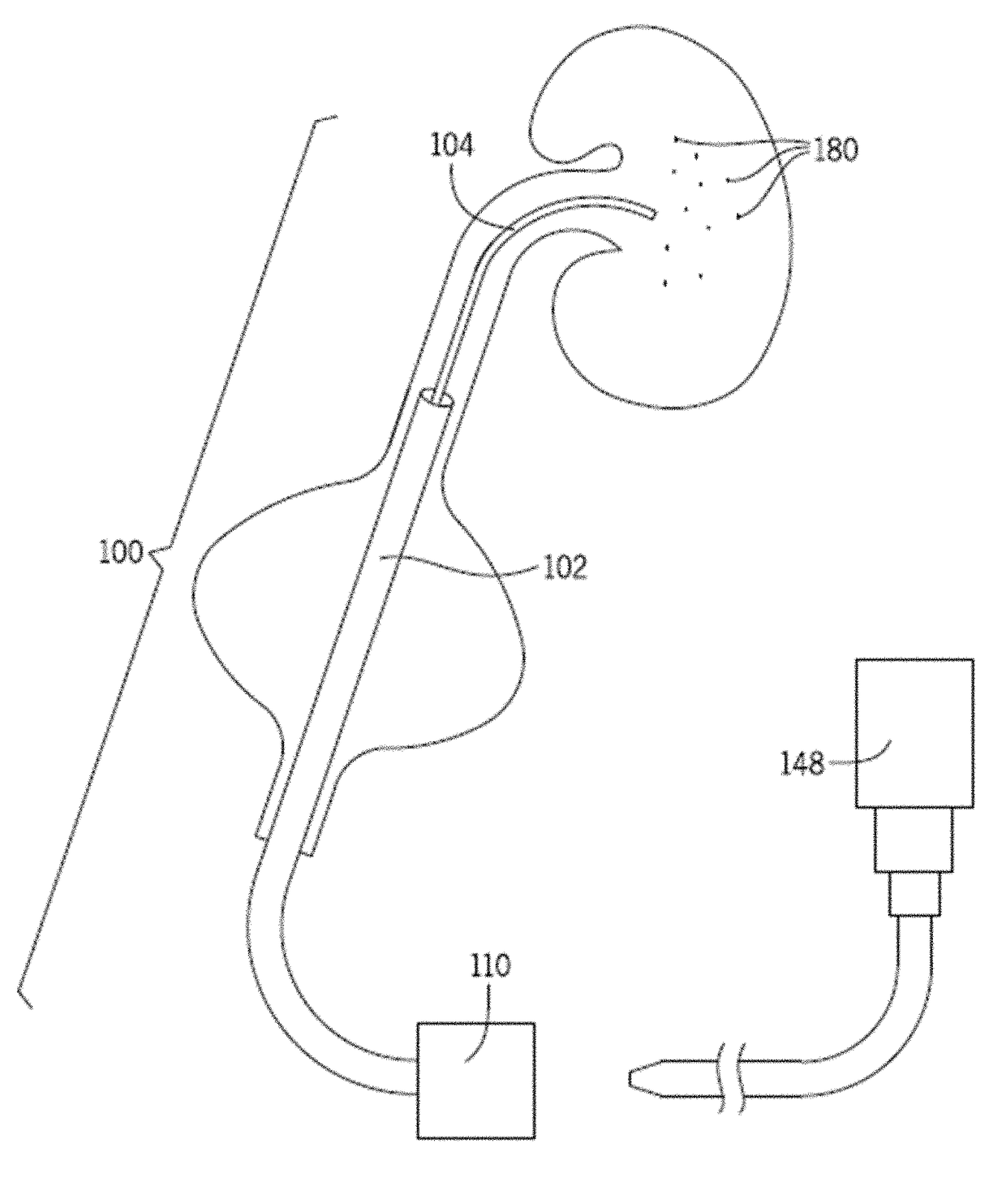
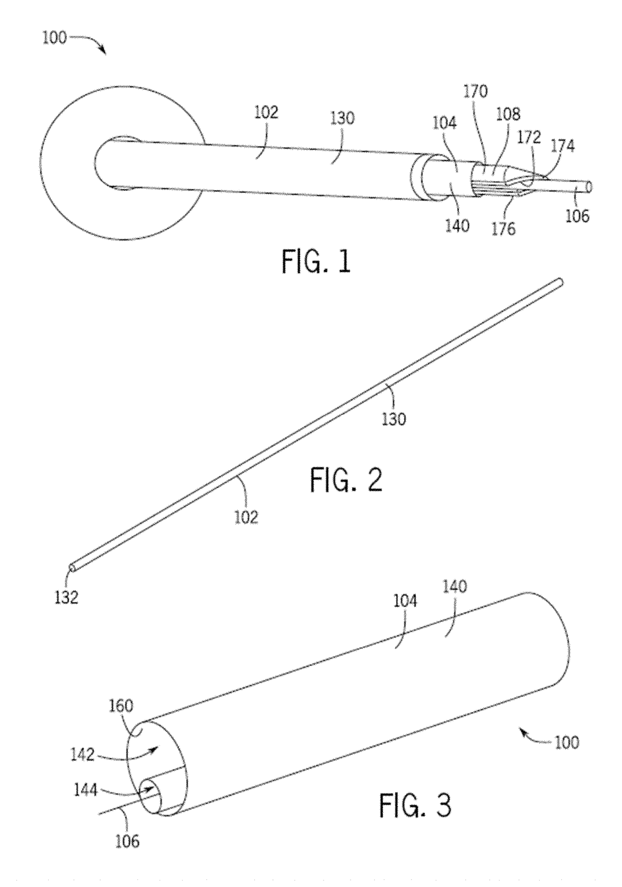
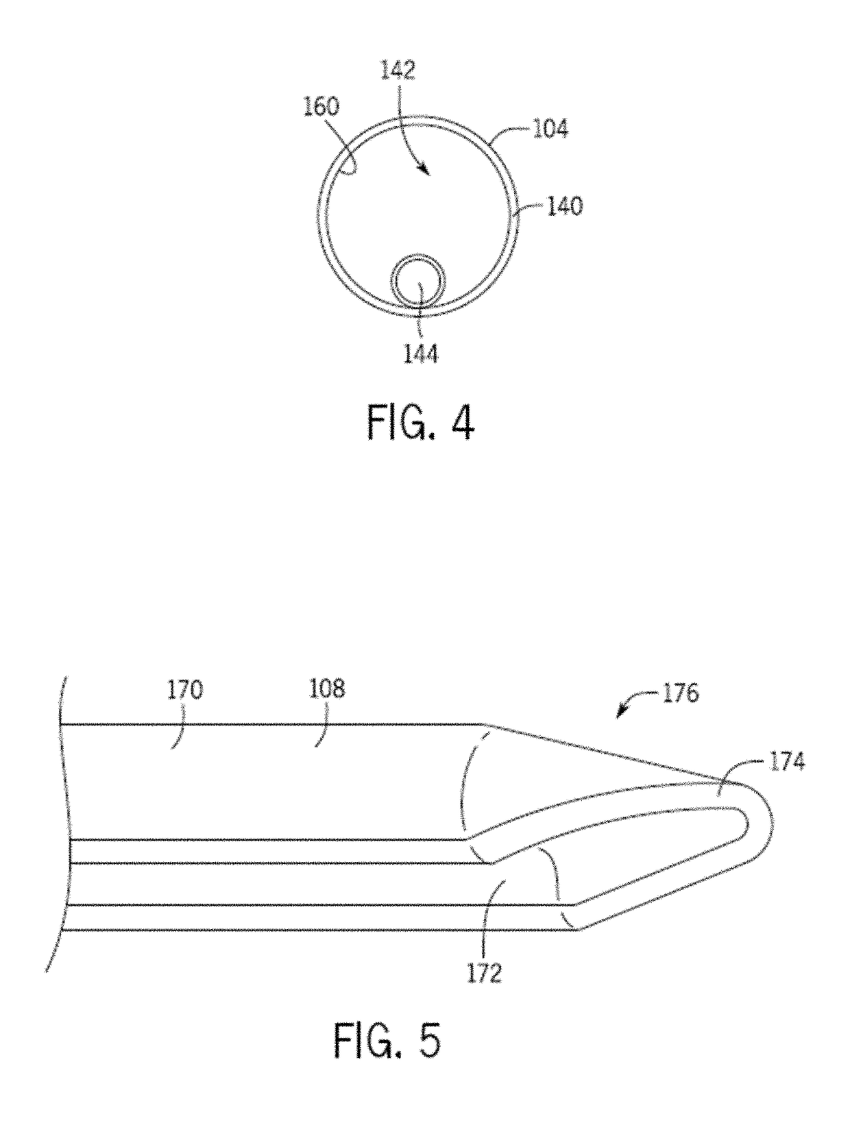
[0046]Referring generally to FIGS. 1-8, a removal device 100 includes a sheath 102, a vacuum tube 104, and a navigation mechanism 106. The removal device 100 optionally includes an introducer core 108 adapted to assist in positioning one or more portions of the removal device 100 in a passageway. The removal device 100 further optionally includes a valve 110 that is in communication with, and assists in controlling suction that is supplied to the vacuum tube 104. One or more of the sheath 102, navigation mechanism 106, and / or introducer core 108 may be optional for use with the removal device 100. For example, in one configuration, the sheath 102 is omitted from the removal device 100.

[0047]As best seen in FIGS. 7 and 8, the removal device 100 is designed to be positioned in a passageway of a patient (e.g., urinary tract), and in particular, into a patient's ureter 112. The removal device 100 includes a renal end 114 designed to be positioned proximate the patient's kidney 116, and ...


PUM


Abstract

In accordance with some configurations, systems and methods for guided removal from an in vivo subject are provided. In some configurations, a method for removing an object is provided. The method comprising, guiding a flexible tube through an in vivo subject's ureter, wherein the flexible tube comprises at least a first passageway and a second passageway. Positioning a distal end of the first passageway adjacent to the object. Infusing saline solution through the second passageway while suction is off. Removing the object through the first passageway with at least a portion of the saline solution.

Description

CROSS-REFERENCE TO RELATED APPLICATIONS[0001]This application is a continuation-in-part, under 35 U.S.C. §120, of U.S. application Ser. No. 14 / 774,418, filed Sep. 10, 2015, which is a National Stage, under 35 U.S.C. §371, of International Application No. PCT / US2014 / 026037, filed Mar. 13, 2014, which claims the benefit, under 35 U.S.C. §119(e), of U.S. Provisional Application No. 61 / 783,239, filed Mar. 14, 2013. Each of the foregoing applications is hereby incorporated herein by reference in its entirety for all purposes.BACKGROUND OF THE INVENTION[0002]The present invention relates to systems and methods for the guided removal of objects in vivo. In particular, the invention is directed to a removal device adapted to traverse compact areas utilizing a navigation mechanism, and more specifically, to capture and / or remove debris through a vacuum tube that is in communication with a suction source.[0003]Kidney stones are a common medical problem that negatively impact millions of indiv...

Claims


Application Information

Patent Timeline
Patent Type & Authority Applications(United States)
IPC IPC(8): A61B17/22A61B1/307A61B18/26A61M3/02A61B1/00A61M25/09A61B18/00
CPCA61B17/22A61B1/307A61B1/00135A61B1/00154A61M25/09A61B18/26A61B2018/00982A61B2017/22079A61B2017/22074A61B2217/007A61B2218/002A61B2218/007A61M3/0279A61M3/0283A61B2017/22039A61B2018/00511A61B2217/005A61B1/012A61M1/774A61M1/77
Inventor EISNER, BRIAN HOWARD
Owner THE GENERAL HOSPITAL CORP
Learn More