Applicator for cryoanesthesia and analgesia

a technology for analgesics and cryoanesthesia, applied in the field of applications of cryoanesthesia and analgesia, can solve the problems of limited methods of anesthesia, pain is a major limitation factor, and local pharmacologic anesthesia usually requires a painful injection, so as to achieve efficient heat spreading and dissipation, the effect of achieving the desired cooling and/or duration performance, and quickly and reliably maintaining a predetermined temperatur

Active Publication Date: 2017-10-26
RGT UNIV OF MICHIGAN
View PDF7 Cites 23 Cited by
  • Summary
  • Abstract
  • Description
  • Claims
  • Application Information

AI Technical Summary

Benefits of technology

[0004]Pain is a major limiting factor in many common procedures performed in the inpatient and ambulatory care settings. A very abbreviated list includes skin biopsy, fine needle aspiration biopsy, IV insertion, vaccination, injections (including injection of anesthetics), blood draws, central line placements, and finger and heal pricks for blood analysis (glucose measurement). Pharmacologic anesthesia is a primary method of pain reduction, but the delivery of local pharmacologic anesthesia usually requires a painful injection. Other methods of providing anesthesia include the application of cold temperatures through ice, liquid evaporation, or low temperature substances. These methods of anesthesia are limited in part by the lack of temperature control and the inability to tightly focus the tissue area receiving anesthesia. The present device improves patient comfort by providing tightly controlled, focal cooling to the tissue needing anesthesia or analgesia.
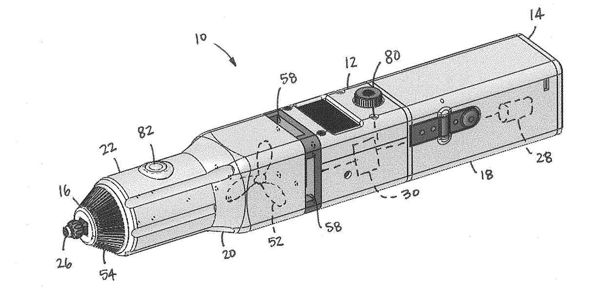
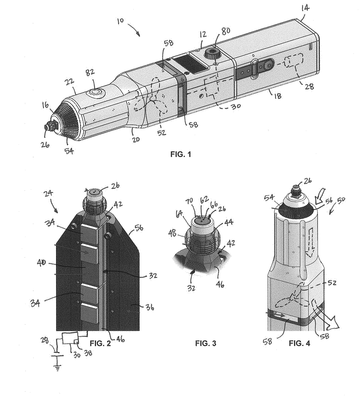
[0048]In some embodiments, cryoanesthesia device 10 can comprise a replaceable / disposable tip coating 70 to provide a sterile surface for ocular contact and to mitigate formation of an ice adhesion between cryoanesthesia device 10 and the patient's eye. In some embodiments, tip coating 70 can comprise a hydrophobic polymer layer to mitigate ice adhesion between the cryoanesthesia device and tissue.

Problems solved by technology

Pain is a major limiting factor in many common procedures performed in the inpatient and ambulatory care settings.
Pharmacologic anesthesia is a primary method of pain reduction, but the delivery of local pharmacologic anesthesia usually requires a painful injection.
These methods of anesthesia are limited in part by the lack of temperature control and the inability to tightly focus the tissue area receiving anesthesia.
The primary limitations of IVT are patient discomfort, ocular surface bleeding, and the time constraints of treating the vast number of patients requiring this therapy.
These drawbacks relate to the difficulty of delivering ocular anesthesia to the highly vascularized ocular surface.
Current methods of local anesthesia have unique drawbacks and patients often experience discomfort during and after intraocular injections.
This has led to severe strain on clinic work flow, as IVT is a time-consuming procedure.
These injections are painful, and ophthalmologists typically choose one of two anesthesia options for IVT.
The second option is to provide minimal anesthesia via topical drops, which is more time efficient, but results in significant patient pain.
Thermoelectric cooling provides reliable refrigeration as well as precise temperature control by direct electric feedback, which is hard to achieve with other available cooling techniques such as liquid evaporation, Joule-Thomson cooling, a thermodynamic cycle (e.g., a Stirling cooler or vapor compression refrigeration cycle), an endothermic reaction, or a low-temperature substance (e.g., liquid nitrogen).
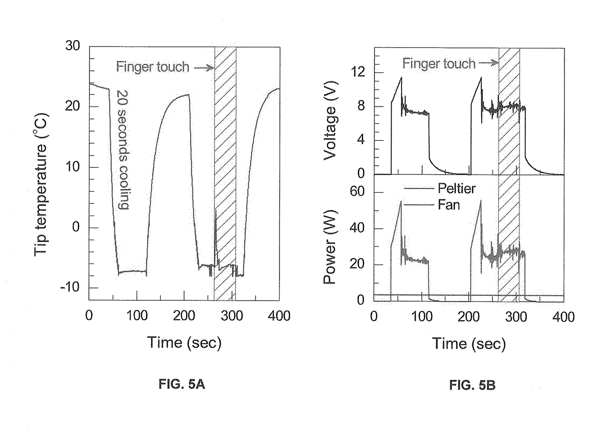
However, current thermoelectric (Peltier) modules have a low coefficient of performance (COP) and do not provide sufficient cooling power flux to maintain tissue at a temperature relevant for anesthesia (e.g., −5° C.) if a single unit is placed with its cooling surface in contact with tissue.

Method used


Image

  • Applicator for cryoanesthesia and analgesia
  • Applicator for cryoanesthesia and analgesia
  • Applicator for cryoanesthesia and analgesia

Examples


Embodiment Construction

[0023]Example embodiments will now be described more fully with reference to the accompanying drawings.

[0024]Example embodiments are provided so that this disclosure will be thorough, and will fully convey the scope to those who are skilled in the art. Numerous specific details are set forth such as examples of specific components, devices, and methods, to provide a thorough understanding of embodiments of the present disclosure. It will be apparent to those skilled in the art that specific details need not be employed, that example embodiments may be embodied in many different forms and that neither should be construed to limit the scope of the disclosure. In some example embodiments, well-known processes, well-known device structures, and well-known technologies are not described in detail.

[0025]The terminology used herein is for the purpose of describing particular example embodiments only and is not intended to be limiting. As used herein, the singular forms “a,”“an,” and “the” ...


PUM


Abstract

A handheld cryoanesthesia or analgesia device for cooling a target area on cutaneous membranes, mucous membranes, and tissue of the mucocutaneous zone having an elongated body and a thermoelectric cooling system disposed within the elongated body. The thermoelectric cooling system is configured to physically contact and thermally couple the target area of the cutaneous membranes, mucous membranes, and tissue of the mucocutaneous zone to induce cryoanesthesia or analgesia. The thermoelectric cooling system includes a thermally-conductive cold tip, a thermally-conductive cooling power concentrator thermally coupled to the cold tip, at least one Peltier unit module thermally coupled to the cooling power concentrator, a heatsink thermally coupled to at least one Peltier unit module, a power source, at least one thermal sensor, and a controller operably outputting a control signal to the Peltier unit module to maintain a predetermined temperature.

Description

CROSS-REFERENCE TO RELATED APPLICATIONS[0001]This application is a continuation of U.S. application Ser. No. 15 / 079,132, filed on Mar. 24, 2016, which claims the benefit of U.S. Provisional Application No. 62 / 237,793, filed on Oct. 6, 2015, and U.S. Provisional Application No. 62 / 138,444, filed on Mar. 26, 2015. The entire disclosures of the above applications are incorporated herein by reference.FIELD[0002]The present disclosure relates to a device to deliver rapid anesthesia or analgesia through cooling of biological tissue, such as cutaneous membranes, mucous membranes, or tissue of the mucocutaneous zone. In some exemplary embodiments, the cryoanesthesia device can deliver rapid anesthesia to the surface of the eye, or other biological tissue, at an injection site to enable more comfortable delivery of medication directly into the eye via intravitreal injection therapy (IVT), retrobulbar injection therapy, subtenon injection therapy, subconjunctival injection therapy, intracamer...

Claims


Application Information

Patent Timeline
Patent Type & Authority Applications(United States)
IPC IPC(8): A61M5/42A61M5/32A61M5/315A61F7/00A61F9/00A61M5/20
CPCA61F2007/0075A61M2210/0612A61F2007/0004A61M2202/048A61F2007/0087A61F2007/0095A61M5/422A61F2007/0086A61M5/322A61M5/315A61M2005/206A61F7/00A61F2007/0078A61F9/0008A61M5/20A61F7/007A61F2007/0052
Inventor BESIRLI, CAGRI GIRAYSMITH, STEPHENPIPE, KEVIN P.KIM, GUN-HO
Owner RGT UNIV OF MICHIGAN
Why Eureka
Try Eureka