Evaporated fuel processing device

a technology of evaporation fuel and processing device, which is applied in the direction of functional valve types, machines/engines, separation processes, etc., can solve the problem of incorrect determination of the start position of the valve, and achieve the effect of accurate determination

Active Publication Date: 2017-10-26
AISAN IND CO LTD
View PDF5 Cites 8 Cited by
  • Summary
  • Abstract
  • Description
  • Claims
  • Application Information

AI Technical Summary

Benefits of technology

[0016]When the flow control valve reaches the valve-opening start position after the valve opening operation thereof is started, and as a consequence, the fuel tank and the canister are communicated with each other, the evaporated fuel is supplied to the engine. At that time, an air-fuel ratio of the engine can be instantaneously changed due to the evaporated fuel. The valve-opening start position of the flow control valve can be determined by detecting such changes of the air-fuel ratio. In the present disclosure, the valve-opening start position of the flow control valve is determined based on changes of the inner pressure of the fuel tank detected by the inner pressure sensor. However, when the changes of the air-fuel ratio are additionally used in order to determine the valve-opening start position, the valve-opening start position may be more accurately determined. Further, instead of the changes of the air-fuel ratio, changes of a feedback correction value of the air-fuel ratio used in control of the air-fuel ratio of the engine may be detected and additionally used in order to determine the valve-opening start position.

Problems solved by technology

Therefore, when the valve-opening start position is determined based on the decrease in the inner pressure, such a valve-opening start position may be incorrectly determined.

Method used


Image

  • Evaporated fuel processing device
  • Evaporated fuel processing device
  • Evaporated fuel processing device

Examples


first embodiment

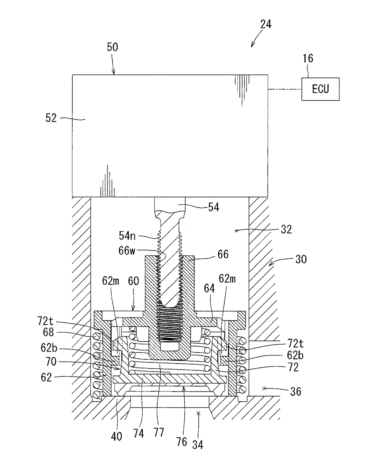
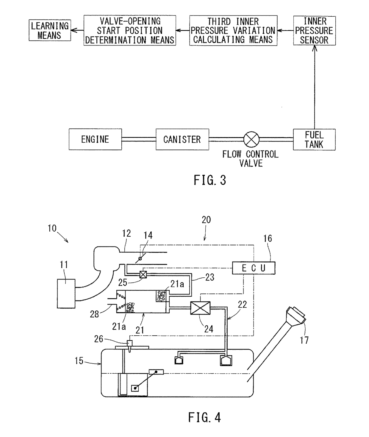
[0030]FIGS. 4 to 8 show the present disclosure. As shown in FIG. 4, in the embodiment, an evaporated fuel processing device 20 is attached to an engine system 10 of a vehicle.

[0031]In FIG. 4, the engine system 10 is a known engine system in which an air-fuel mixture is fed into an engine body 11 via an intake passage 12. Air may be fed into the intake passage 12 via a throttle valve 14 while a flow rate thereof is controlled. Fuel may be fed into the intake passage 12 via a fuel injection valve (not shown) while a flow rate thereof is controlled. The throttle valve 14 and the fuel injection valve may respectively be connected to a control unit (ECU) 16. The throttle valve 14 may be configured to send signals representing opening degrees of the throttle valve 14 to the control circuit 16. The fuel injection valve may be configured such that a valve-opening time thereof can be controlled by the control unit 16. Further, the fuel may be fed into the fuel injection valve from a fuel tan...

second embodiment

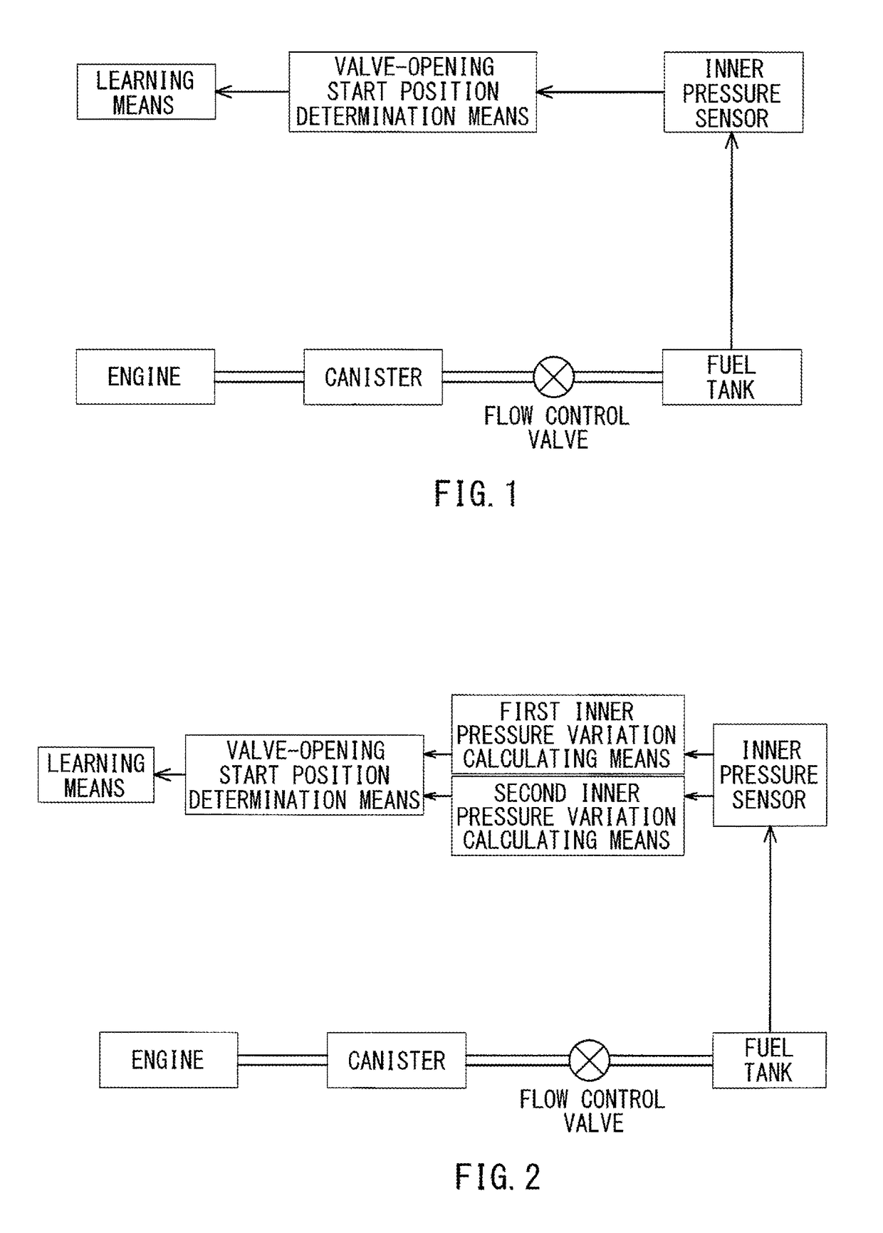
[0057] the valve-opening start position of the closing valve 24 may be determined based on the range of variation between the differential pressure Vp calculated this time and the differential pressure Vp calculated previous time. Therefore, even if the tank pressure gradually varies due to external factors such as changes in temperature, the valve-opening start position can be determined without any influence.

[0058]Furthermore, in the second embodiment, the processing in Steps S2 to Step S6 and Step S20 may be omitted. This omission may contribute to reduce a processing program for determination of the valve-opening start position of the closing valve 24, so as to reduce a processing time.

[0059]The processing Step S2 to Step S5 and Step S8 to Step S12 in each of the embodiments described above may correspond to a valve-opening start position determination means of the first aspect of the present disclosure. Further, the processing Step S2 to Step S5 may correspond to a first inner ...


PUM

PropertyMeasurementUnit
travel distanceaaaaaaaaaa
axial travel distanceaaaaaaaaaa
pressureaaaaaaaaaa

Abstract

An evaporated fuel processing device includes a flow control valve that is used as a valve to be installed in a pathway connecting a canister and a fuel tank. The device includes an inner pressure sensor configured to detect a pressure in an interior space of the fuel tank as an inner pressure, a valve-opening start position determination means configured to calculate a second order differential value of the inner pressure after a valve opening operation of the flow control valve is started and to determine a valve opening position of the flow control valve as a valve-opening start position when the second order differential value is equal to or greater than a first predetermined value, and a learning means configured to store the valve-opening start position as a learned value that is used when a valve-opening control of the flow control valve is performed.

Description

CROSS-REFERENCE TO RELATED APPLICATIONS[0001]The present application is a National Phase entry of, and claims priority to, PCT Application No. PCT / JP2015 / 074147, filed Aug. 27, 2015, which claims priority to Japanese Patent Application No. 2014-176954, filed Sep. 1, 2014, both of which are incorporated herein by reference in their entireties.STATEMENT REGARDING FEDERALLY SPONSORED RESEARCH OR DEVELOPMENT[0002]Not applicable.BACKGROUND[0003]The present disclosure relates to an evaporated fuel processing device in which a flow control valve is used as a valve to be installed in a pathway connecting a fuel tank and a canister, and in which the flow control valve is held in a valve-closed condition when a stroke amount corresponding to an axial travel distance of a valve movable element to a valve seat is equal to or less than a predetermined amount from an initial condition, so as to be capable of holding the fuel tank in a hermetically closed condition.[0004]An evaporated fuel process...

Claims


Application Information

Patent Timeline
Patent Type & Authority Applications(United States)
IPC IPC(8): B60K15/035F02M25/08B01D53/04F16K17/04B60K15/03F02M37/00
CPCB60K15/03519F02M25/0854F02M25/0836F16K17/048B60K2015/03296F02M37/00B01D2253/102B01D2257/7022B01D2259/4516B01D53/0407B60K2015/0321B60K2015/03302B60K2015/03514F02M25/08F02M25/089
Inventor KIMOTO, JUNYAMIYABE, YOSHIKAZU
Owner AISAN IND CO LTD
Why Eureka
Try Eureka