
Liquid Heating Appliance

a heating appliance and liquid technology, applied in the field of liquid heating appliances, can solve the problems of high running cost, relatively high cost of electric water heaters, and considerable thermal loss in operation, and achieve the effect of reducing heat loss and good insulation

Active Publication Date: 2017-10-26
CAVE PIERS S J
View PDF0 Cites 6 Cited by
  • Summary
  • Abstract
  • Description
  • Claims
  • Application Information

AI Technical Summary

Benefits of technology

The patent describes an appliance that can store and heat water using a vacuum flask. This appliance has a small inlet to receive water, which is then heated and stored in a separate chamber. The heat is controlled to be released when needed, without wasting energy. The appliance is insulated to prevent heat loss and has a heat reflective interior. It can be powered by solar or other external sources and has flow control regulators to control the flow of water through the appliance. This design saves energy and water, and provides quick hot water at the tap.

Problems solved by technology

On the whole electrical water heaters are relatively expensive and their thermal losses in operation are quite considerable and they do not represent an efficient means for storing or using electrical energy but are used for convenience, compact size and often due to lack of alternatives for a specific location (other fuel sources not available / viable) even though running costs can be high.
Electrical water heaters give the greatest flexibility and especially facilitate use of renewable energy, eg from electrical energy harvested from PV arrays or wind turbines et cetera, but fail to store or use the energy to best effect.

Method used


Image

  • Liquid Heating Appliance
  • Liquid Heating Appliance
  • Liquid Heating Appliance

Examples


Embodiment Construction

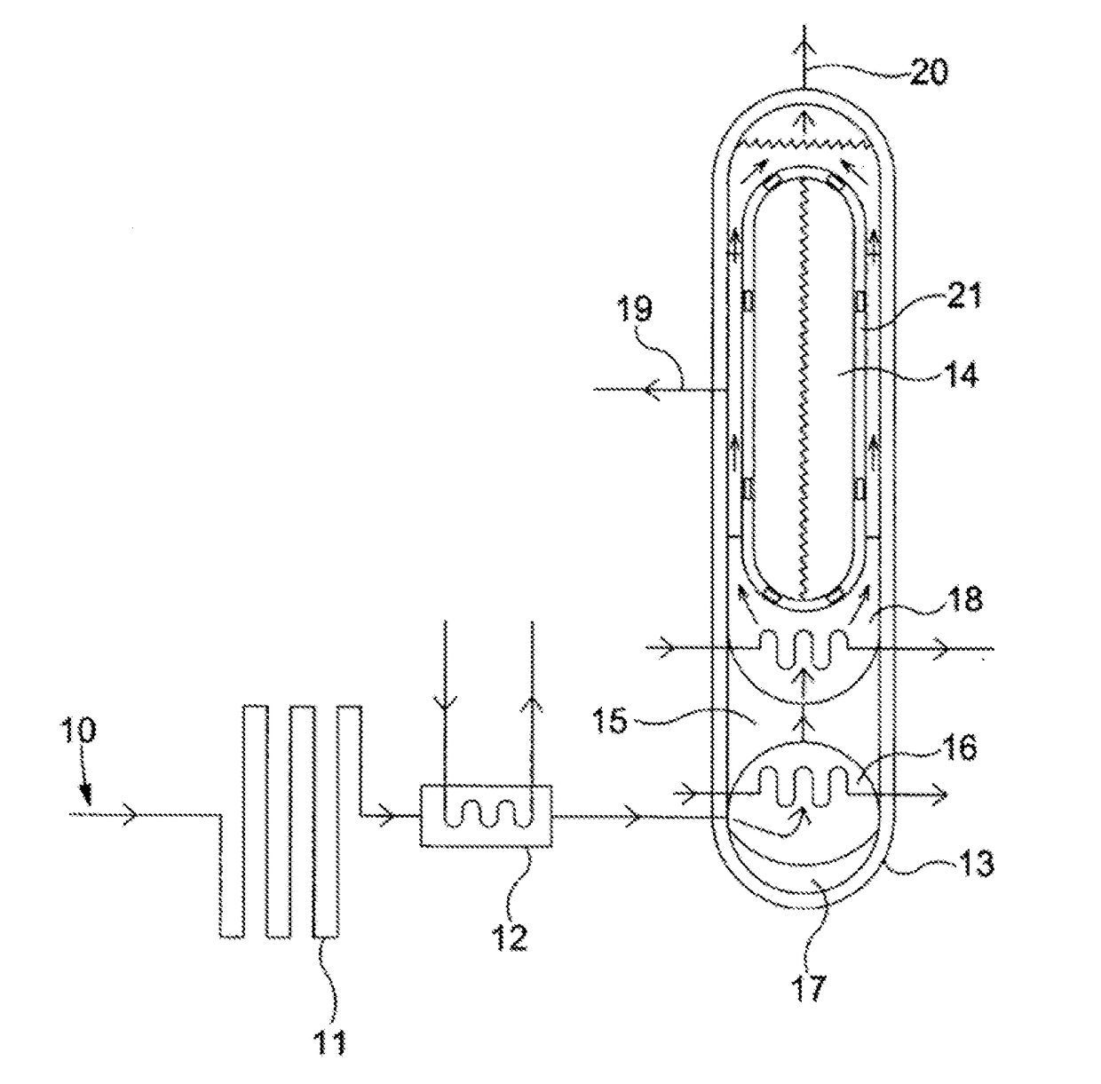
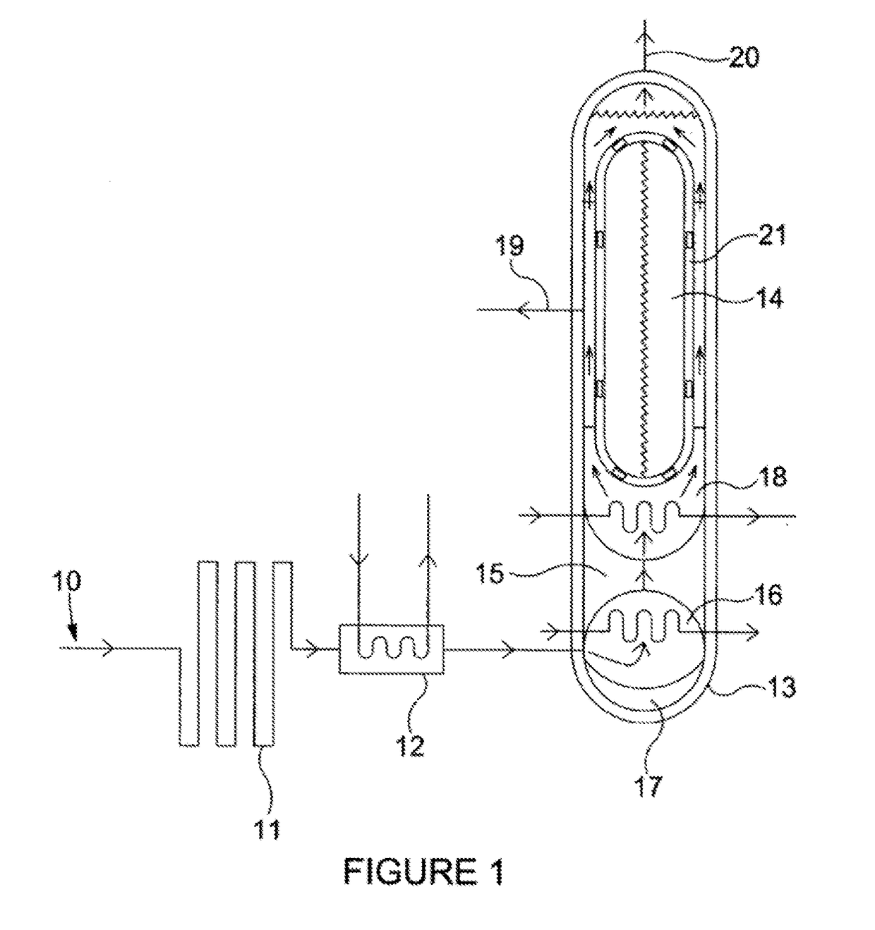
[0041]Referring to FIG. 1, the illustrated embodiment of the appliance is a plumbed system that receives incoming pressurised cold water from a mains water supply. The mains water supply will commonly be at a pressure of between 1 and 4 bar and by virtue of that pressure is driven through the system without need of pumping. The water flows through the system from the inlet 10 (at the left end of the system as illustrated) to the outlet 20 (at the top right hand end as illustrated). The cold water entering the system at the water inlet 10 first passes through a non-return valve to enter an aerial heat exchanger 11 of high external surface area (suitably with plates or fins and similar to a radiator) and which serves to warm the water passing through it to around the ambient room temperature of the room in which the system is installed. The aerial heat exchanger 11 has below it a drip tray for any vapour in the room condensing on it, the drip tray having a surface area sufficient to c...


PUM


Abstract

A liquid heating appliance for heating water or other liquids, suitably to a target temperature of from 55° C. to around boiling point, includes a primary heat chamber or body (heat source chamber) that is thermally insulated and which in use contains a high thermal density heat storing liquid or solid; and a secondary chamber alongside the primary chamber through which a liquid to be heated is passed in use. The appliance has a heat transfer feature to selectively transfer thermal energy from the heat-storing liquid or solid to the liquid to be heated in the secondary chamber. The secondary chamber is preferably a conduit through which the liquid to be heated is able to flow and the thus heated liquid can be delivered to a tap as hot water for a range of uses. Water may also be heated for a central heating system for space heating.

Description

CROSS REFERENCE TO RELATED APPLICATIONS[0001]This application is a national stage entry of PCT application no. PCT / GB2015 / 000220, having an international filing date of Jul. 28, 2015 which claims the benefit of Gb application no. 1413358.1 filed on July 28, 204, the entirety of both applications are hereby incorporated by reference herein.BACKGROUND OF THE INVENTIONField of the Invention[0002]The present invention concerns improvements in and relating to liquid heating appliances, including systems for heating water or other liquids, whether for central heating of buildings or for hot water delivery / dispensing. Hot water delivered is suitably delivered at high temperatures of from about 55° C. to around boiling point, for example for use for hot beverages, for cooking, washing or for other purposes.Background of the Invention[0003]Liquid heating appliances for heating water are for the most part generally not pressurised systems but designed to operate at atmospheric pressure or at ...

Claims


Application Information

Patent Timeline
IPC IPC(8): F01K7/16F24D17/00F24H7/00F28D20/00F24D18/00F28F13/00
CPCF01K7/16F24D17/001F24D17/0089F28F2270/00F28D20/0034F28F2013/008F24H7/002F24H7/0241F24D17/0021F24D2200/02F24D2200/14F24D2200/20F24D2220/08F24H2250/10F28D2020/0082Y02B10/20Y02B10/70F28D2020/0078Y02E70/30Y02B30/18Y02E60/14F24D2101/40F24D2103/17F24D18/00F24D2103/13F24H1/0018F24H1/18
Inventor CAVE, PIERS ST JOHN SPENCER
Owner CAVE PIERS S J
Learn More