Actuator unit for controlling hydraulic pump

a technology of hydraulic pump and actuator, which is applied in the direction of positive displacement liquid engine, machine/engine, gearing, etc., can solve the problems of d2 being prone to twisting stress and the cost of the configuration of d2 being grea

Active Publication Date: 2017-10-26
KANZAKI KOKYUKOKI MFG
View PDF18 Cites 0 Cited by
  • Summary
  • Abstract
  • Description
  • Claims
  • Application Information

AI Technical Summary

Benefits of technology

[0011]An object of the invention is to provide a simple configuration to ensure an accurate and stable interlocking connection between a telescopic movement of an actuator of an HST control mechanism, e.g., a servomechanism, and a rotational movement of a trunnion shaft of a movable swash plate of the HST even if the servo unit that should be separated from the HST is distant from the trunnion shaft. Moreover, in the case where the HST control mechanism includes a servo unit as combination of the actuator and a valve, minimization of the servo unit and facility in attachment and detachment of the servo unit are also included in the object of the invention.
[0013]Therefore, the rotation of the servo unit surely converts the telescopic linear movement of the actuator to the rotational movement of the rotary member without a twisting stress caused by the differential movement between the telescopic linear movement of the actuator and the rotational movement of the rotary member. Moreover, due to the first pivot pivoting the servo unit, the unification of the actuator and the valve assembled together as the servo unit is ensured so as to improve assembly of the actuator and the valve and so as to ensure facilitation of the servo unit in its attachment and detachment.
[0015]Therefore, while the servo unit is rotated in response to the telescopic movement of the actuator, the servo unit weight balance is improved and the rotation degree required for the servo unit is reduced.
[0017]Therefore, the servo unit includes no biasing device, thereby being improved in minimization and reduction of costs. Moreover, the existing telescopic member for rotating a trunnion shaft can be applied as the telescopic member provided with the biasing device. Only if the servo unit including no biasing device is additionally provided, the entire HST control mechanism is configured as an assembly of the actuator and the valve having the function to return the HST to the neutral state.
[0019]Therefore, the existing arm, which is pivoted on the casing rotatably centered on the trunnion shaft, and which is pivotally connected to the existing telescopic member provided with the biasing device can be applied as the first arm. When the servo unit is attached, the first and second arm and the link can easily be provided as the rotary member interlockingly connected to both the telescopic member provided with the biasing device and the actuator of the servo unit only if the second arm is added to be pivoted on the casing and to be connected to the first arm via the link.

Problems solved by technology

However, in the case of D1, the part of the vehicle pivotally supporting the cylinder bottom is weighed on or loaded eccentrically because it cantilevers the cylinder, so that it is liable to a twisting stress due to the rotation of the cylinder.
As a result, the cost of the configuration of D2 becomes great.
However, the actuator needs a biasing means that biases the actuator to a position corresponding to a neutral position of the movable swash plate, i.e., a neutral position of the HST.

Method used


Image

  • Actuator unit for controlling hydraulic pump
  • Actuator unit for controlling hydraulic pump
  • Actuator unit for controlling hydraulic pump

Examples


first embodiment

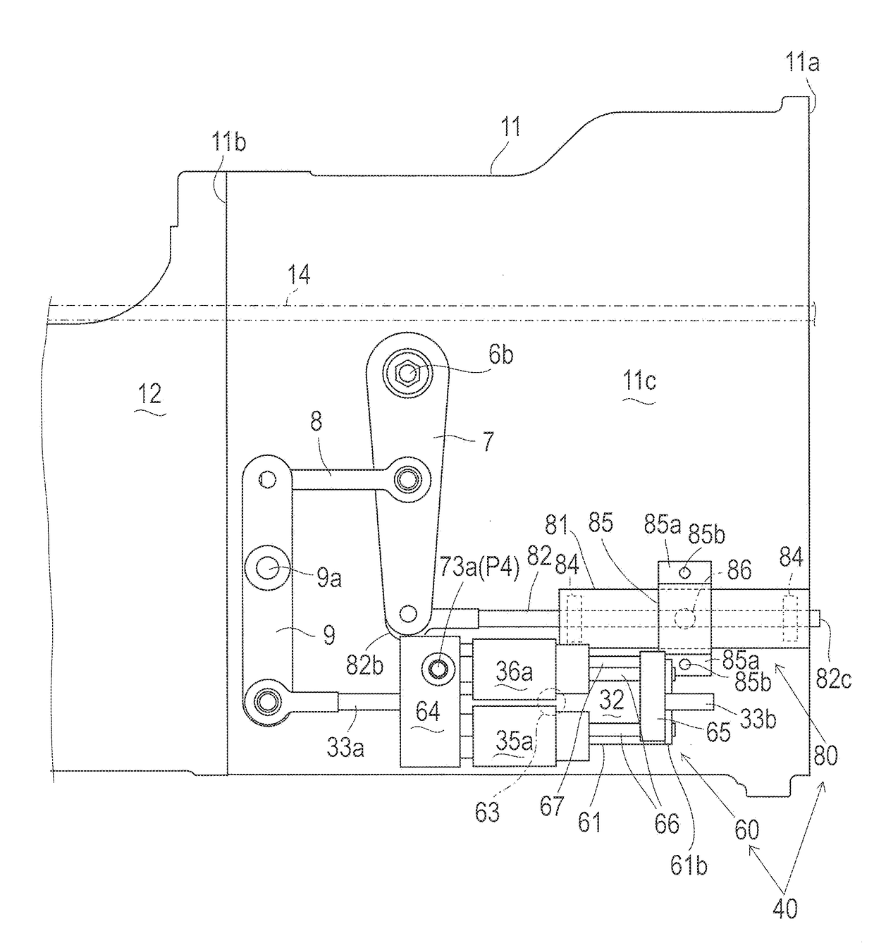
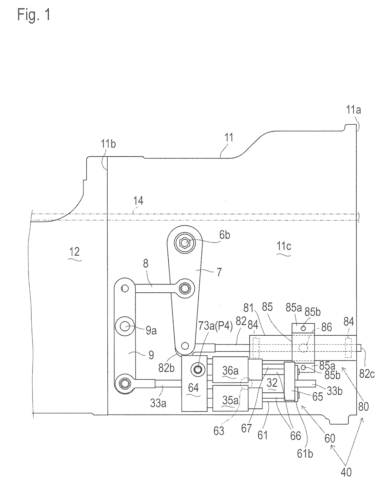
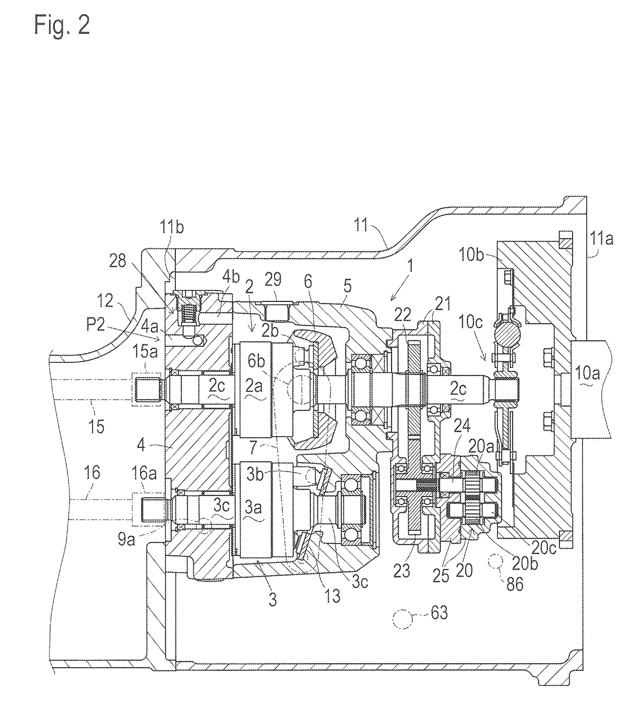
[0095]In this embodiment, right and left trunnion shafts of movable swash plate 6 are defined as a short trunnion shaft 6a and long trunnion shaft 6b. Bearing cap 8 and bearing bracket 9 are formed therein with respective bearing holes 8a and 9a. Bearings 17 are provided in respective bearing holes 8a and 9a so as to fit respective inner peripheral surfaces of bearing cap 8 and bearing bracket 9. A fluid seal 18 is fitted in bearing hole 9a of bearing bracket 9. Trunnion shaft 6a is inserted into bearing hole 8a, and trunnion shaft 6b into bearing hole 9a, so that trunnion shafts 6a and 6b are journalled by bearing cap 8 and bearing bracket 9 via respective bearings 17. Therefore, flange 8b of bearing cap 8 covers a tip of short trunnion shaft 6a so that the tip of trunnion shaft 6a does not project outward from HST housing 5. On the other hand, lateral bearing hole 9a penetrates bearing bracket 9 so that an outer end of bearing hole 9a is open at flange 9b of bearing bracket 9. The...

second embodiment

[0112]Referring to FIGS. 18 to 23, servo units 30A, 30B, 30C, 30D and 30E serving as modifications of servo unit 30 will be described. However, description of the component elements designated by the same reference numerals as those used for description of the embodiment shown in FIGS. 14 to 17 will be omitted except for some special cases, on the assumption that they are identical or similar to those designated by the same reference numerals in the embodiment of FIGS. 14 to 17.

[0113]Servo unit 30A will be described with reference to FIG. 18. Servo unit 30A has a servo housing 31A that is similar to servo housing 31 of servo unit 30 except that a lower portion of notch 31g formed in servo housing 31A is expanded further downward so as to serve as a gallery 31m, and drain fluid hole 31d extended distally from drain fluid hole 31c is not formed but a drain fluid hole 31k is formed in servo housing 31A so as to extend proximally from drain fluid hole 31c and so as to be open at proxim...


PUM


Abstract

An HST control mechanism includes a rotary member, a servo unit, a telescopic member, and a biasing device. The rotary member for controlling a displacement of a hydrostatic transmission (HST) is pivoted outside of a casing incorporating the HST. The servo unit includes a telescopically movable actuator and a valve controlling the telescopic movement of the actuator. The actuator is interlockingly connected to the rotary member. The servo unit is pivotally supported on the casing via a first pivot. The servo unit rotates centered on the first pivot as the rotary member rotates according to the telescopic movement of the actuator hydraulically controlled by the valve. The telescopic member is pivotally supported on the casing via a second pivot. The telescopic member is provided with the biasing device that biases the telescopic member and the rotary member toward a position corresponding to a neutral state of the HST.

Description

CROSS-REFERENCE TO RELATED APPLICATIONS[0001]This application is a continuation of U.S. application Ser. No. 14 / 817,922, filed Aug. 4, 2015, which claims priority to Japanese Patent Applications No. 2014-161495, filed on Aug. 7, 2014, and No. 2014-162729, filed on Aug. 8, 2014.BACKGROUND OF THE INVENTIONField of the Invention[0002]The present invention relates to a control mechanism for controlling the output rotary speed and direction of a hydrostatic transmission (hereinafter, “HST”). Especially, the control mechanism is a servomechanism including a servo unit that combines a telescopic (linearly movable) actuator and a valve.Related Art[0003]As disclosed by JP 2002-250437 A (hereinafter, “D1”), JP H06-100278 B (hereinafter, “D2”), and JP 2013-096449 A (hereinafter, “D3”), an HST used as a transmission for a tractor is usually disposed in a casing that also serves as a vehicle body frame (chassis) of the tractor. Also, as disclosed by D1, D2 and D3, it is well-known that a piston ...

Claims


Application Information

Patent Timeline
Patent Type & Authority Applications(United States)
IPC IPC(8): F16H61/4069F16H39/04F04B23/04F16H61/431F04B1/00
CPCF16H39/04F16H61/431F04B23/04F04B1/00F16H61/4069F16H47/02
Inventor MATSUURA, JUNIWAKI, KOJITSUJI, TOMOYUKIKAMADA, MINORUKANENOBU, HIDEKISASAHARA, KENGO
Owner KANZAKI KOKYUKOKI MFG
Why Eureka
Try Eureka