
Test film for detecting surface particles in clean room

a test film and surface particle technology, applied in the direction of material analysis, instruments, withdrawing sample devices, etc., can solve the problems of product defect, fatal product defect, product yield reduction, etc., to ensure the cleanliness of the clean room, easy and fast check whether or not the clean room is contaminated, and maintain the clean room

Active Publication Date: 2017-11-02
JEDEX
View PDF2 Cites 7 Cited by
  • Summary
  • Abstract
  • Description
  • Claims
  • Application Information

AI Technical Summary

Benefits of technology

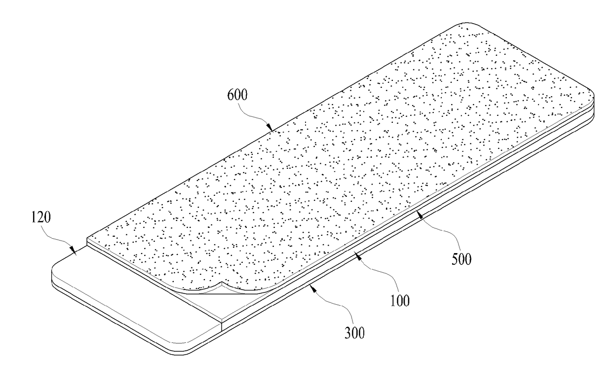
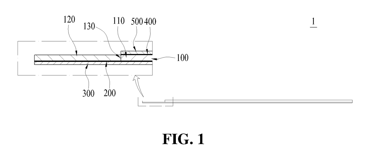
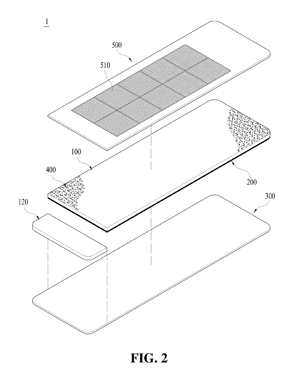
The present invention makes it easy to check if a clean room is contaminated or not. It allows for quick and easy inspection by collecting surface particles from an object and measuring their number, size, distribution, etc. The invention also provides a protective film that can prevent contamination and scratches during operations such as printing, movement, circulation, and cutting. Furthermore, the invention allows for accurate measurement during microscopic inspection by using a substrate that does not bend well and a release film that protects the adhesive layer surface. Bubbles generated on the surface can also be easily detected to confirm the clean room state.

Problems solved by technology

For example, in the semiconductor manufacturing process, it is pointed out that pattern defects caused by deposition of particles oscillated from an automation device or the like on the surface of the wafer are the main causes of the yield reduction of the product.
As such, if the particles are present at the site where the product is manufactured, the particles may be transferred to the product during the manufacturing process and thus may cause fatal product defect.
These particles are accumulated on ceilings, walls, floors, production and measurement equipment, various equipment and the like of the site where the product is manufactured, and are attached to the surface of the worker's clothing, and when causing the movement of airflow due to the movement of robots, workers and products, and the spatial imbalance of temperature, the surface particles accumulated on the surface of workers, objects, or their adjacent portions will be transferred to contaminate the product, thereby causing product defect.
However, since the above-described prior arts require to separately purchase an expensive particle measuring device for particle measurement, there is a problem not only that a lot of cost is required, but also that the operation of the equipment is complicated, a long time is required for inspection, and a large space is required because of the large size of the equipment.
Also, particle measuring devices according to the above-described prior art can measure the number, size, or distribution of the whole particles in the clean room, but there is a problem in that it is difficult to identify the sampled specimen and it is impossible to judge from which object the collected particles are generated, and to judge the place where the object entered along with a large amount of particles is located, and thus it is difficult to control contamination by particles in the clean room.
In addition, although there is a method of cleaning the surface of the object to be measured with clean water and then counting the particles with a counter for counting particles in the liquid, there is a problem in that it is difficult to detect particles which are dissolved in water and liquefied because the particles are washed with water and detected in water.

Method used


Image

  • Test film for detecting surface particles in clean room
  • Test film for detecting surface particles in clean room
  • Test film for detecting surface particles in clean room

Examples


Embodiment Construction

[0032]Hereinafter, a detailed description for implementing the test film for detecting the surface particles of the clean room according to the present invention will be described in detail by exemplifying embodiments with reference to the drawings.

[0033]According to a report on “Research on Development of Super Clean Room of Class 1” issued by the Ministry of Science and Technology in October 1992, it is generally known that adhesion of particles occurred in a clean room to the surface is the most important matter in view of contamination control in a clean room, wherein the particles floating in the air in the clean room reach very close to the surface due to Brownian diffusion, turbulent diffusion, external force and the like, and at this time, the potential energy exists and the particles have a minimum energy in the immediate vicinity of the surface of the object to be measured by Van der Waals force or the like, and in general, when the minimum value of this energy (φ) is smal...


PUM


Abstract

The present invention relates to a test film for detecting surface particles in a clean room in order to prevent inferior products by measuring the contamination level of the clean room using the surface particles. The present invention provides a test film for detecting surface particles in a cleanroom, the test film comprising a substrate which has a predetermined thickness and is formed of a transparent synthetic resin material; a first adhesive layer which is formed at one side of the substrate and collects the surface particles; a release film which is adhered to the first adhesive layer and is separated from the first adhesive layer when the surface particles are collected; a second adhesive layer which is formed at the other side of the substrate; and a protective film which is adhered to the second adhesive layer so as to protect the substrate and has gradations indicated thereon. According to the present invention, there is an effect in that it is possible to easily and quickly check whether or not a clean room is contaminated by collecting, on the adhesive layer-applied surface of a substrate to which an adhesive is applied, surface particles adhered to an object to be measured, and then measuring the number, size, distribution, etc. of the surface particles with the naked eye or using instruments such as a light, a magnifier, a microscope, or the like.

Description

TECHNICAL FIELD[0001]The present invention relates to a test film for detecting surface particles in a clean room, more particularly, a test film for detecting surface particles in a clean room in order to prevent product defect by measuring the contamination level by the surface particles in the clean room.BACKGROUND ART[0002]Generally, as the industry is getting sophisticated, there is an increasing need to control particles such as dust and the like in production sites as well as in office environments, and thus a clean room was introduced to keep the production site clean at all times and thus to prevent adverse effects on the product by the particles.[0003]Such a clean room refers to a space where contamination control is performed by controlling the concentration of the particles floating in the air within a indicated cleanliness level limit, wherein the space is also controlled and managed for environmental conditions such as temperature, humidity, room pressure, illuminance,...

Claims


Application Information

Patent Timeline
IPC IPC(8): G01N15/02G01N1/20G01N21/88G01N1/04G01N1/02
CPCG01N15/0205G01N21/8803G01N2001/028G01N1/20G01N1/04G01N1/02G01N2001/2833G01N15/0612
Inventor KIM, JIN HO
Owner JEDEX
Learn More