Cathode current collector for a hall-heroult cell

a technology of cathode current collector and hallheroult cell, which is applied in the direction of electrolysis process, electrodes, electrolysis components, etc., can solve the problems of low current efficiency of the process, inability to reduce energy consumption, and high cost of copper insert solutions, so as to increase the conductivity of carbon cathodes, increase the useful height of cathodes, and increase the effect of cathodes

Active Publication Date: 2017-11-09
NOVALUM SA
View PDF3 Cites 7 Cited by
  • Summary
  • Abstract
  • Description
  • Claims
  • Application Information

AI Technical Summary

Benefits of technology

[0032]Using cathode current collector bars according the invention, increases the conductivity of the carbon cathode enabling the useful height of the cathode block to be increased by from 10% to 30% depending on the original cathode design and the design of the upper contact profile of the highly conductive metal of the new collector bar. By increasing the height of the cathode block, the useful lifetime of the cathode and hence the

Problems solved by technology

The existence of waves leads to a loss of current efficiency of the process and does not allow decreasing the energy consumption under a critical value.
The Prior Art solutions respond to a given

Method used


Image

  • Cathode current collector for a hall-heroult cell
  • Cathode current collector for a hall-heroult cell
  • Cathode current collector for a hall-heroult cell

Examples


first embodiment

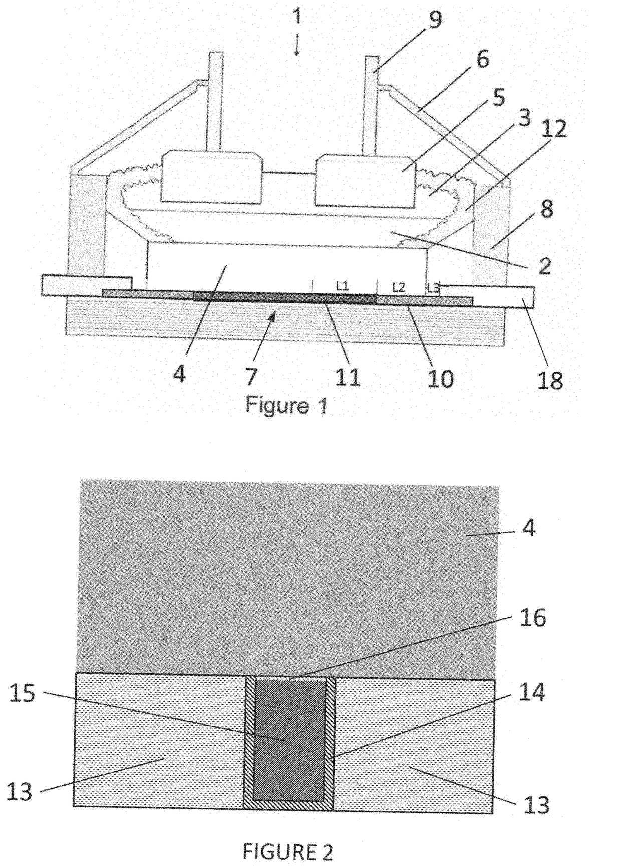
[0045]FIG. 2 is a cross section through collector bar showing a U-shaped profile.

second embodiment

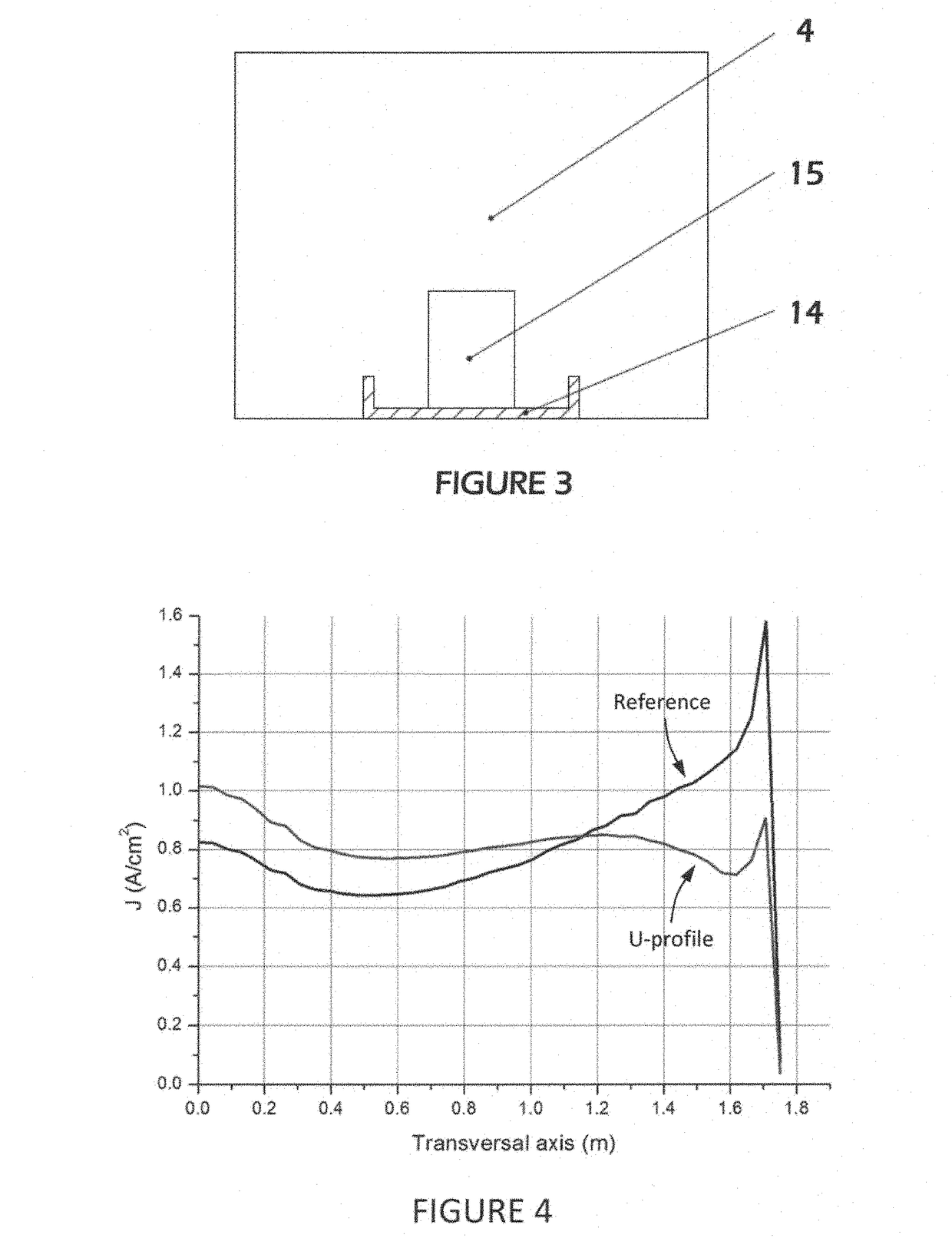
[0046]FIG. 3 is a cross section through collector bar showing another U-shaped profile.

[0047]FIG. 4 is a graph of current density across a cathode equipped with a current collector according to the invention with a U-shaped profile, and a reference cathode.

[0048]FIG. 5A is a cross section through a cathode showing the highly conductive material of the collector bar glued to a carbon cathode.

[0049]FIG. 5B is a cross section through a cathode showing the highly conductive material of the collector bar in direct electrical contact with the carbon cathode.

[0050]FIG. 6 is a cross section through another embodiment of a cathode current collector assembly according to the invention.

[0051]FIG. 7 illustrates how the highly conductive material of the cathode current collector bar is connected to a steel bar (transition joint) for leading the current outside the cell.

[0052]FIG. 8 shows an alternative connection of the highly conductive metal of the cathode current collector bar to a steel bar ...


PUM

PropertyMeasurementUnit
Temperatureaaaaaaaaaa
Weightaaaaaaaaaa
Pressureaaaaaaaaaa

Abstract

The invention relates to an electrolytic cell (1) for the production of aluminium (2) including collector bars structure modifications (13,14,15,16) under the cathode (4), namely a copper collector bar held in a U-shaped profile or directly embedded into the cathode. This leads to an optimized current distribution in the liquid aluminium metal (2) and/or inside the carbon cathode allowing for operating the cell at lower voltage. The lower voltage results from either a lower anode to cathode distance (ACD), and/or to lower voltage drop inside the carbon cathode from liquid metal to the end of the collector bar.

Description

FIELD OF INVENTION[0001]The invention relates to the production of aluminium using the Hall-Héroult process; in particular to the optimization of the collector bars for the decrease of energy consumption, maximization of the current efficiency and increase of cell productivity.BACKGROUND OF THE INVENTION[0002]Aluminium is produced by the Hall-Héroult process, by electrolysis of alumina dissolved in cryolite based electrolytes at temperature up to 1000° C. A typical Hall-Héroult cell is composed of a steel shell, an insulating lining of refractory materials and a carbon cathode holding the liquid metal. The cathode is composed of a number of cathode blocks in which collector bars are embedded at their bottom to extract the current flowing through the cell.[0003]A number of patent publications have proposed different approaches for minimizing the voltage drop between the liquid metal to the end of the collector bars. WO2008 / 062318 proposes the use of a high conductive material in comp...

Claims


Application Information

Patent Timeline
IPC IPC(8): C25C3/16C25C7/02
CPCC25C7/025C25C3/16
Inventor VON KAENEL, RENESPINETTI, GUALTIERO
Owner NOVALUM SA
Why Eureka
Try Eureka