
Pump

a technology of syringe pump and syringe body, which is applied in the field of syringe pump, can solve the problems of inability to know for sure whether the user cannot always be certain if the syringe pump is dispensing fluid, and the conventional syringe pump also suffers, so as to reduce the height and therefore the volume of the system, the effect of easy connection and moulding

Active Publication Date: 2017-11-09
OXFORD NANOPORE TECH LTD
View PDF1 Cites 2 Cited by
  • Summary
  • Abstract
  • Description
  • Claims
  • Application Information

AI Technical Summary

Benefits of technology

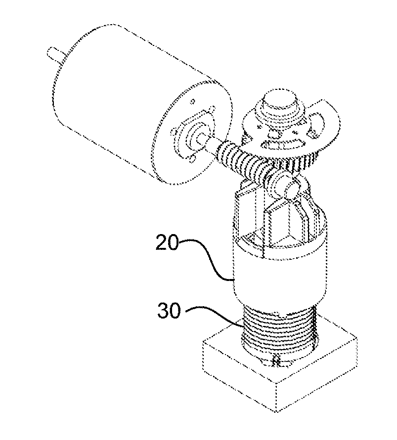
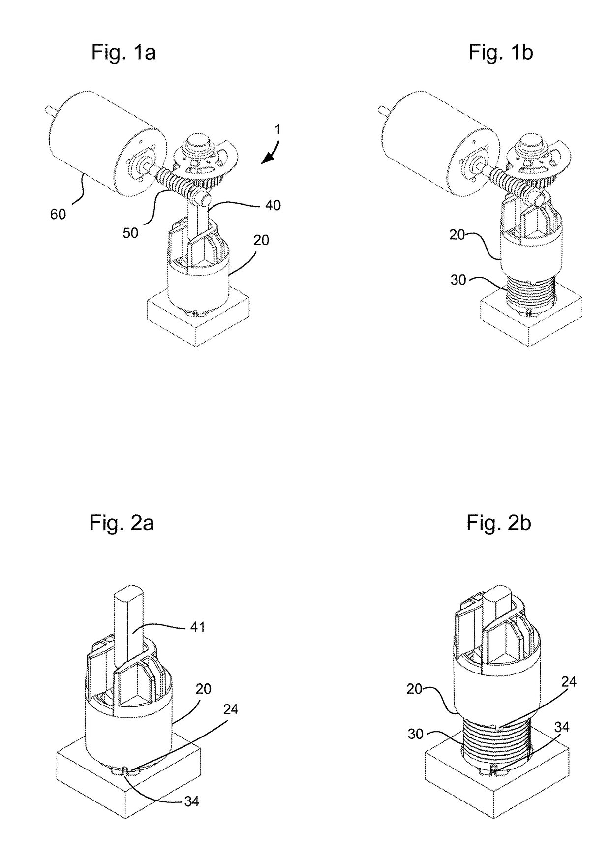
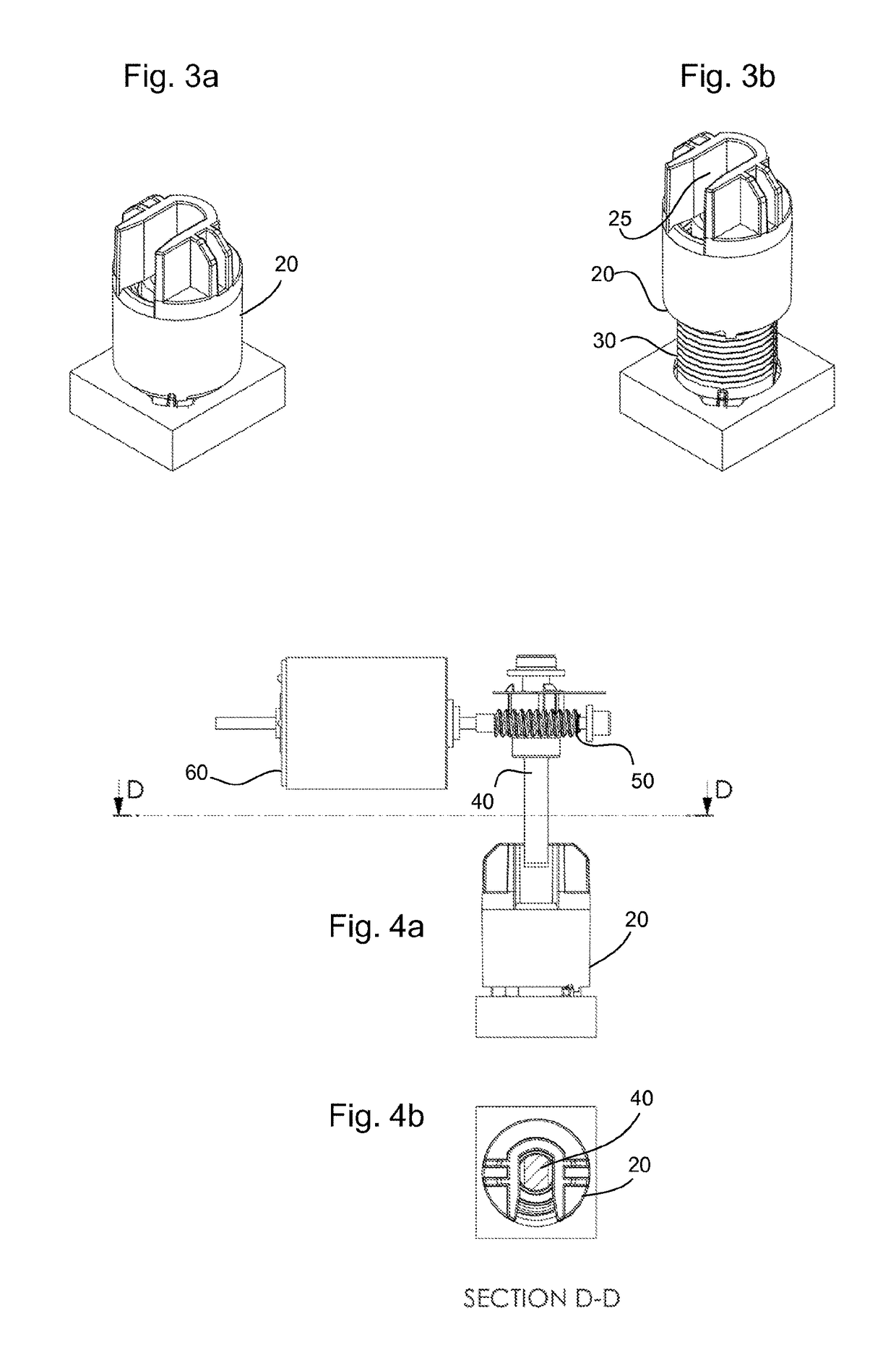
The design achieves a compact, space-efficient pump that minimizes contamination risks and provides precise control over fluid dispensing, suitable for microfluidic and nanopore applications by translating rotational motion into linear motion without compromising accuracy or increasing the pump's profile.

Problems solved by technology

As a result, the syringe pump often requires much more space than the syringe which it drives.
Another problem with such pumps is that the user cannot always be certain if the pump is dispensing fluid when the actuator is displaced, because the actuator may not be in contact with the syringe plunger when the actuator is first moved.
Conventional syringe pumps also suffer from a problem related to the seal formed by the syringe plunger with the syringe barrel.
This raises possible fluid contamination / interaction issues.
In fluidic and microfluidic applications, and biological fluidic applications in particular, it is undesirable to introduce materials into the system which might somehow react with the fluids or leach contaminants into the process fluids and somehow affect the experiment being performed in an unexpected and / or unquantifiable manner.
Further, the use of an elastic sealing material causes a characteristic stick / slip jump when first moving the plunger.
This is caused due to high static friction between the elastic sealing material and barrel, which must be overcome to start the plunger moving.
Even after the static friction has been overcome, the presence of the elastic O-ring results in a relatively large amount of dynamic friction (and hence a corresponding large required driving force) that must be overcome to keep the plunger moving.
This makes fine control of the syringe difficult, especially when first beginning to move the plunger.
However, this approach is expensive and is therefore not well suited to the mass manufacture of disposable syringes.
The use of metal may also introduce fluid contamination considerations.

Method used


Image

  • Pump
  • Pump
  • Pump

Examples


Embodiment Construction

[0040]The present invention has identified that conventional syringe pumps are unsuitable for many fluidic and microfluidic applications. For example, WO 2009 / 077734 hereby incorporated by reference, relates to the formation of layers of amphiphilic molecules, in which nanopores can be deployed to provide an environment which can be useful, for example, for sequencing polynucleotides. This is an example of a ‘nanopore application’, referred to below. The formation of the bi-layer, the provision of the nanopores, and the subsequent provision of test fluids require careful control of the fluidic environment, both in mechanical and chemical terms. In the case of pumping lipid to form bi-layers, an extremely slow pumping speed is required. An example range is between 1 μl / s to 0.1 μl / s. The stick / slip issues with conventional elastic-sealing syringe pumps makes control of such flow rates extremely problematic, and can make repeatability of experiments very difficult. This is particularl...


PUM

PropertyMeasurementUnit
flow ratesaaaaaaaaaa

Abstract

A pump for use in low-profile applications comprises a barrel for holding fluid; and a piston that converts a rotational driving force into a longitudinal driving motion within the barrel. The pump provides space saving advantages by reducing the need for external equipment and mechanisms around the pump for providing actuation or moving the actuating mechanism.

Description

RELATED APPLICATIONS[0001]This application is a 35 U.S.C. 371 national stage filing of International Application No. PCT / GB2012 / 052233, filed on Sep. 11, 2012, which claims priority to Great Britain Application NO. 1116020.7, filed on Sep. 15, 2011, and Great Britain Application No. 1116019.9, filed on Sep. 15, 2011. The contents of the aforementioned applications are hereby incorporated by reference.FIELD OF INVENTION[0002]The present invention relates to pumps and how to provide a low-profile pump for dispensing small amounts of fluid.BACKGROUND[0003]Syringe pumps provide a mechanism for controlling the motion of the piston within the barrel and therefore the displacement of fluid in the syringe. The syringe used by the pump may be an integral part of the pump itself, or can commonly be a disposable part that can be used and replaced, and may be a syringe that can also be used manually. A syringe pump theoretically allows for a straightforward determination of the amount of fluid ...

Claims


Application Information

Patent Timeline
Patent Type & Authority Applications(United States)
IPC IPC(8): F04B53/14F04B13/00F04B9/02F04B7/06A61M5/315A61B17/88F04B17/03B29C70/68A61M5/145B29L31/26
CPCF04B17/03F04B7/06A61M5/145F04B53/143B29L2031/26B29C70/68A61M5/31513F04B13/00F04B9/02A61B17/8822A61M5/31586A61M5/31528A61M5/31515A61M2205/0222B29L2031/7544A61M2207/00F16J15/328F16J15/3208
Inventor JONES, ANTHONYUPSDELL, JONATHAN
Owner OXFORD NANOPORE TECH LTD
Learn More