Calibrating Device for Measuring and Calibrating the Center of Gravity of a Remote Control Aircraft or an Airfoil Thereof

a remote control aircraft and center of gravity technology, which is applied in the direction of instruments, structural/machine measurement, transportation and packaging, etc., can solve the problems of inability to equip remote control aircraft or helicopters with such calibrating devices, unstable flying of aircrafts, and affecting the flying of remote control aircraft, so as to improve the utility of calibrating devices, improve the convenience of carrying the calibrating device, and reduce the length of the crossbar

Inactive Publication Date: 2017-11-09
FONG BONG ENTERPRISE
View PDF22 Cites 16 Cited by
  • Summary
  • Abstract
  • Description
  • Claims
  • Application Information

AI Technical Summary

Benefits of technology

[0028]In the form shown, the calibrating device further includes a box having a plurality of lateral boards and a bottom board. The bottom board may be fixed to the bottom frame. Each of the plurality of lateral boards is pivotally coupled with the bottom board. A chamber is formed between the plurality of lateral boards and the bottom board. The crossbar, the first support, the second support and the control unit are received in the chamber. As such, the box can protect the crossbar, the first support, the second support, the control unit or the bottom frame from damage during the transportation, thereby improving the convenience in carrying the calibrating device of the embodiment of the disclosure.
[0029]In the form shown, a mirror is arranged on one of the plurality of lateral boards or arranged between two opposite lateral boards of the plurality of lateral boards. The mirror faces the chamber. As such, the mirror can reflect the bottom image of the aircraft (or the airfoil), allowing the user to view the indicated location of the center of gravity of the aircraft (or the airfoil) from the above. Advantageously, the user does not have to stoop so low to check under the aircraft (or the airfoil) for the location of the center of gravity, improving the utility of the calibrating device.
[0030]In the above structures, the calibrating device of the embodiment of the disclosure uses two receiving portions of the first support to respectively support two main wheels or two airfoils of an aircraft, and uses the supporting portion of the second support to support a fuselage of the aircraft. Thus, the aircraft can be properly supported, and the length of the crossbar can be reduced. This advantageously reduces the overall volume and weight of the calibrating device, improving the convenience in carrying the calibrating device. Furthermore, since the two receiving portions of the first support and the supporting portion of the second support are used as three fulcrums to support the aircraft, it does not need to use the clamping member to fix the aircraft. Thus, the production process of the calibrating device is simplified and the utility of said calibrating device is improved. Besides, the calibrating device according to the embodiment of the disclosure can be used by various aircrafts with different sizes without having to change the length of the crossbar. This further simplifies the production process of the calibrating device and improves the utility of said calibrating device.

Problems solved by technology

However, the model remote control aircrafts or helicopters cannot be equipped with such calibrating devices due to the consideration of cost and weight.
Furthermore, the flying of the remote control aircrafts tends to be affected by the external factors such as wind speed and humidity.
If the location of the center of gravity is not properly calibrated, the flying of the aircrafts will be unstable, which even causes crash of the aircrafts due to the difficulty in manipulating the aircrafts.
However, such types of the calibrating devices have the disadvantage of inconvenient use, such that they are not suitable for use with a heavier aircraft.
Said types of the calibrating devices also have the disadvantages of inconvenient measuring processes and inconvenient adjustment of the location of the center of gravity, and cannot be carried to an aerodrome for use.
As a result, it would be inconvenient to carry the calibrating device 9.
If the user accidentally knocks against the aircraft “P” during the calibration process of the location of the center of gravity, the aircraft “P” may be overturned or even fall off the two supports 92.

Method used


Image

  • Calibrating Device for Measuring and Calibrating the Center of Gravity of a Remote Control Aircraft or an Airfoil Thereof
  • Calibrating Device for Measuring and Calibrating the Center of Gravity of a Remote Control Aircraft or an Airfoil Thereof
  • Calibrating Device for Measuring and Calibrating the Center of Gravity of a Remote Control Aircraft or an Airfoil Thereof

Examples


Embodiment Construction

[0049]The term “couple” used hereinafter refers to the linkage between two devices through the use of a wired medium, a wireless medium or the combination thereof (such as a heterogeneous network) for data transmission purposes, as it can be readily appreciated by the persons skilled in the art.

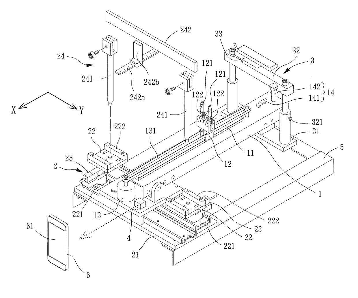
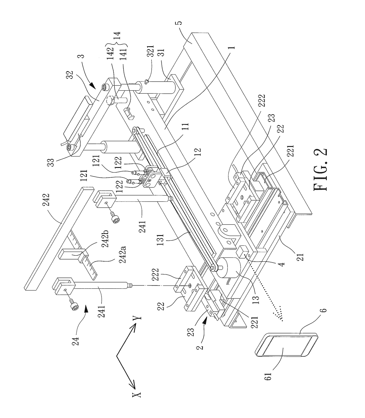
[0050]FIG. 2 shows a calibrating device for measuring and calibrating the center of gravity (CG) of a remote control (RC) aircraft or an airfoil thereof according to an embodiment of the disclosure. The center of gravity of a remote control aircraft is abbreviated to “CG of a RC aircraft” throughout the specification hereinafter. The calibrating device includes a crossbar 1, a first support 2 and a second support 3. The first support 2 and the second support 3 can be arranged at two ends of the crossbar 1, respectively.

[0051]The crossbar 1 includes a longitudinal rail 11 arranged in an extending direction of the crossbar 1, as well as a slider 12 movably engaged with the longitudinal rail 11....


PUM


Abstract

A calibrating device for measuring and calibrating a center of gravity of a remote control aircraft or an airfoil thereof is provided. The calibrating device includes a crossbar, a first support, a second support and a control unit. The crossbar is arranged along a longitudinal axis, and includes a longitudinal rail and a slider. The slider is movably engaged with the longitudinal rail. The crossbar includes a drive member coupled with the longitudinal rail or the slider. The slider includes a pointer. The first support includes a seat and two receiving portions which are arranged on the seat and are movable along a transverse axis. The receiving portions are aligned with each other. Each receiving portion includes a load cell. The second support includes a base and a supporting portion, and the supporting portion includes a load cell. The control unit is coupled with the drive member and the three load cells.

Description

BACKGROUND OF THE INVENTION1. Field of the Invention[0001]The present disclosure generally relates to a calibrating device for measuring and calibrating the center of gravity of a remote control aircraft or an airfoil thereof and, more particularly, to a calibrating device that measures the instant location of the center of gravity of a remote control aircraft or an airfoil thereof and accordingly adjusts the location of the center of gravity of the remote control aircraft or the airfoil thereof.2. Description of the Related Art[0002]The location of the center of gravity of an aircraft largely affects the balance, operability and safety of the aircraft. Therefore, some advanced aircrafts such as airplanes or helicopters are often equipped with calibrating devices that are used to measure and calibrate the locations of the centers of gravity. Some advanced aircrafts are even equipped with the calibrating devices that can dynamically adjust the locations of the centers of gravity ther...

Claims


Application Information

Patent Timeline
Patent Type & Authority Applications(United States)
IPC IPC(8): G01M1/12
CPCB64F5/0045G01M1/125B64F5/60G01G19/07
Inventor CHANG, WEN-LIANG
Owner FONG BONG ENTERPRISE
Why Eureka
Try Eureka