Controller premonition using capacitive sensing

a capacitive sensing and controller technology, applied in the field of game controllers and touch sensors, can solve the problems of affecting the experience of users, the disconnection between virtual reality and the user, and the lack of visual feedback of the user's body or extremities, etc., and achieve the effect of sensitivity or resolution of the cirque® corporation touchpad

Inactive Publication Date: 2017-11-16
CIRQUE CORPORATION
View PDF3 Cites 17 Cited by
  • Summary
  • Abstract
  • Description
  • Claims
  • Application Information

AI Technical Summary

Benefits of technology

[0003]The CIRQUE® Corporation touchpad is a mutual capacitance-sensing device and an example is illustrated as a block diagram in FIG. 1. In this touchpad 10, a grid of X (12) and Y (14) electrodes and a sense electrode 16 is used to define the touch-sensitive area 18 of the touchpad. Typically, the touchpad 10 is a rectangular grid of approximately 16 by 12 electrodes, or 8 by 6 electrodes when there are space constraints. Interlaced with these X (12) and Y (14) (or row and column) electrodes is a single sense electrode 16. All position measurements are made through the sense electrode 16.
[0004]The CIRQUE® Corporation touchpad 10 measures an imbalance in electrical charge on the sense line 16. When no pointing object is on or in proximity to the touchpad 10, the touchpad circuitry 20 is in a balanced state, and there is no charge imbalance on the sense line 16. When a pointing object creates imbalance because of capacitive coupling when the object approaches or touches a touch surface (the sensing area 18 of the touchpad 10), a change in capacitance occurs on the electrodes 12, 14. What is measured is the change in capacitance, but not the absolute capacitance value on the electrodes 12, 14. The touchpad 10 determines the change in capacitance by measuring the amount of charge that must be injected onto the sense line 16 to reestablish or regain balance of charge on the sense line.
[0005]The system above is utilized to determine the position of a finger on or in proximity to a touchpad 10 as follows. This example describes row electrodes 12, and is repeated in the same manner for the column electrodes 14. The values obtained from the row and column electrode measurements determine an intersection which is the centroid of the pointing object on or in proximity to the touchpad 10.
[0006]In the first step, a first set of row electrodes 12 are driven with a first signal from P, N generator 22, and a different but adjacent second set of row electrodes are driven with a second signal from the P, N generator. The touchpad circuitry 20 obtains a value from the sense line 16 using a mutual capacitance measuring device 26 that indicates which row electrode is closest to the pointing object. However, the touchpad circuitry 20 under the control of some microcontroller 28 cannot yet determine on which side of the row electrode the pointing object is located, nor can the touchpad circuitry 20 determine just how far the pointing object is located away from the electrode. Thus, the system shifts by one electrode the group of electrodes 12 to be driven. In other words, the electrode on one side of the group is added, while the electrode on the opposite side of the group is no longer driven. The new group is then driven by the P, N generator 22 and a second measurement of the sense line 16 is taken.
[0007]From these two measurements, it is possible to determine on which side of the row electrode the pointing object is located, and how far away. Using an equation that compares the magnitude of the two signals measured then performs pointing object position determination.
[0008]The sensitivity or resolution of the CIRQUE® Corporation touchpad is much higher than the 16 by 12 grid of row and column electrodes implies. The resolution is typically on the order of 960 counts per inch, or greater. The exact resolution is determined by the sensitivity of the components, the spacing between the electrodes 12, 14 on the same rows and columns, and other factors that are not material to the present invention. The process above is repeated for the Y or column electrodes 14 using a P, N generator 24

Problems solved by technology

However, there may be a disconnect between the virtual reality that the user is experiencing through sight and sound, and the actual physical area in which the user is located.
The experience of wearing an HMD may be very disconcerting to users because the user is not typically able to see their own body, arms, legs, feet or hands.
This lack of visual feedback of a user's own body or extremities may be detrimental to the experience of the user and detract from the virtual environment because a user may be limited to only having tactile feedback from the physical object.
The lack of visual clues to the location of the user's own arms, hands, legs and feet may cause the user to stumble or awkwardly reach out to feel for objects.
However, this visual feedback may be lacking in the virtual environment because it may be very difficult to represent a user's hands and fingers in the virtual environment.

Method used


Image

  • Controller premonition using capacitive sensing
  • Controller premonition using capacitive sensing
  • Controller premonition using capacitive sensing

Examples


first embodiment

[0026]Beginning with the understanding that the user's own body parts are not being represented in the virtual environment, the first embodiment is directed to providing visual feedback to the user that indicate how the user is going to interact with a virtual object.

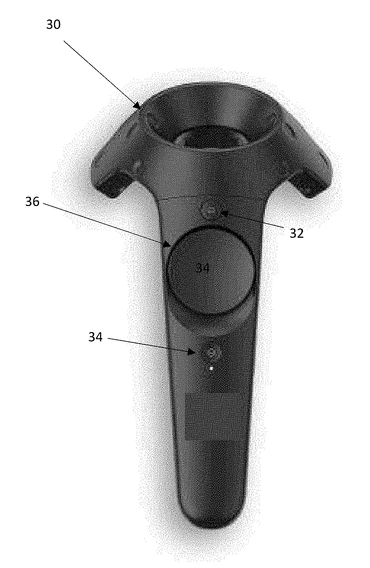
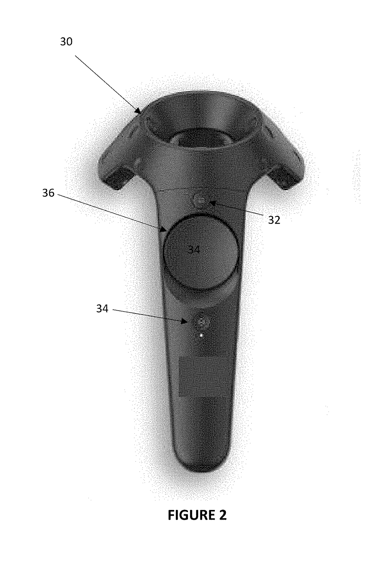
[0027]FIG. 2 is provided as a perspective view of a physical game controller 30. The game controller 30 may be represented in the virtual environment as a handheld device. However, it should be understood that the game controller 30 may appear as a different object in the virtual environment. This virtual object may be similar or different in shape, size, color, texture or any other visual attribute relative to the physical game controller 30. The virtual object may not even show a grip or hand hold where a user is actually holding the game controller 30. What is important is that the user is able to interact the game controller, and the game controller is represented in the virtual environment.

[0028]A first feature of ...

third embodiment

[0043]In the present invention, it may not be the approach of an object toward a capacitive sensor that may cause a change in the virtual environment. Other actions that the user may do with the physical game controller 30 may include but should not be considered as limited to, a change in grip or a change in force applied to the physical game controller. Accordingly, selected portions of the physical game controller 30 may include proximity sensing of the entire game controller. Likewise, selected portions of the physical game controller 30 may include touch sensing of the entire game controller.

[0044]It may be possible to provide an image of a user's hand on the physical game controller 30 for more advanced positional information in the virtual environment. Thus, it may be possible to determine where each finger is resting on the game controller 30. Sensing may be further modified to accomplish grip force sensing for certain games or applications.

[0045]It should be understood that...


PUM


Abstract

A system and method for providing a virtual reality game controller with improved functionality by providing capacitive touch and proximity sensors on the controller to enable additional feedback to the user such that interaction with a physical object such as a game controller may be translated into interaction with a virtual tool in a virtual environment such as providing a visual indication in the virtual environment that a finger or thumb is approaching a button of a physical game controller.

Description

BACKGROUND OF THE INVENTIONField of the Invention[0001]This invention relates generally to game controllers and touch sensors. Specifically, the invention pertains to a system and method for providing a virtual reality game controller with improved functionality by providing capacitive touch and proximity sensors on the controller to enable additional feedback to the user that is particularly useful in a virtual reality environment.Description of Related Art[0002]There are several designs for capacitance sensitive touch sensors which may take advantage of a system and method for providing capacitive touch sensors on the controller to enable additional feedback to the user. It is useful to examine the underlying technology of the touch sensors to better understand how any capacitance sensitive touchpad can take advantage of the present invention.[0003]The CIRQUE® Corporation touchpad is a mutual capacitance-sensing device and an example is illustrated as a block diagram in FIG. 1. In...

Claims


Application Information

Patent Timeline
Patent Type & Authority Applications(United States)
IPC IPC(8): G06F3/044G06T19/00A63F13/21A63F13/28
CPCG06F3/044G06T19/006A63F13/28A63F13/21G06F2203/04101A63F2300/8082G06F3/011G06F3/016G06F3/03547A63F13/211A63F13/216A63F13/219A63F13/214A63F13/285
Inventor STURM, ETHANBAKER, STEVEN H.VINCENT, PAULTAYLOR, DAVID C.
Owner CIRQUE CORPORATION
Why Eureka
Try Eureka