
Self correcting adaptive low light optical payload

a low-light optical payload and self-correction technology, applied in the field of image processing, can solve the problems of low-light frame aggregation employed in the implementations of low-light imaging platforms, which has previously not been applied by others, and is sensitive to motion, so as to reduce underexposure and contrast loss, increase the exposure period, and reduce the effect of underexposur

Active Publication Date: 2017-11-16
RAYTHEON CO
View PDF6 Cites 8 Cited by
  • Summary
  • Abstract
  • Description
  • Claims
  • Application Information

AI Technical Summary

Benefits of technology

The patent describes an imaging platform that can correct distortion caused by motion when taking pictures of a scene. This is particularly useful for airborne and space platforms that have wide fields of view and high angular rates of movement, as well as night-time and low-light imaging platforms that require longer exposure periods. By correcting the induced motion, the platform can increase the exposure period without causing blur and use a smaller aperture, reducing weight, volume, and cost.

Problems solved by technology

In particular, airborne and low-orbit space platforms used for ground imaging, for example, tend to be sensitive to motion due to their wide fields of view and / or high angular rates of movement.
In addition, nighttime and low-light imaging platforms are susceptible to distortion since longer exposure periods for collecting light are required.
Previous use of low light imaging comprises generally stand-alone imagery, and typically is only capable when illumination is sufficient.
The low light frame aggregation employed in the implementations has previously not been applied by others in the field, due to the inability to use said imagery to measure the induced motion and extract eigenvector coefficients due to too little SNR per frame to discern features.

Method used


Image

  • Self correcting adaptive low light optical payload
  • Self correcting adaptive low light optical payload
  • Self correcting adaptive low light optical payload

Examples


Embodiment Construction

[0047]Systems and methods for capturing images are disclosed. In the following description, numerous specific details are set forth. In the other instances, details well known to those skilled in the art may not be set out so as not to obscure the invention. It will be apparent to those skilled in the art in the view of this disclosure that modifications, substitutions and / or changes may be made without departing from the scope and spirit of the invention. In the description that follows, like components have been given the same reference numerals, regardless of whether they are shown in different examples. As noted above, in order to illustrate examples of the present disclosure in a clear and concise manner, the drawings may not necessarily be to scale and certain features may be shown in somewhat schematic form. Features that are described and / or illustrated with respect to one example may be used in the same way or in a similar way in one or more other examples and / or in combina...


PUM


Abstract

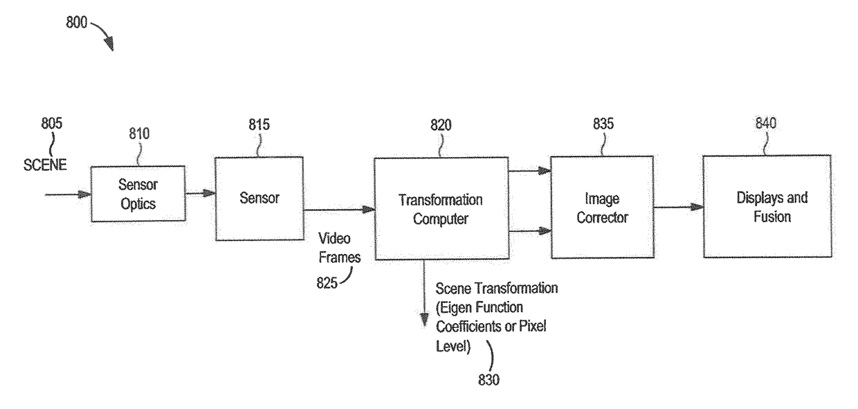
Methods and systems are disclosed for compensating for image motion induced by a relative motion between an imaging platform and a scene. During an exposure period, frames of the scene may be captured respectively in multiple spectral bands, where one of the spectral bands has a lower light level than the first spectral band, and contemporaneous frames include a nearly identical induced image motion. Image eigenfunctions are utilized to estimate the induced image motion from the higher SNR spectral band, and compensate in each of the multiple bands.

Description

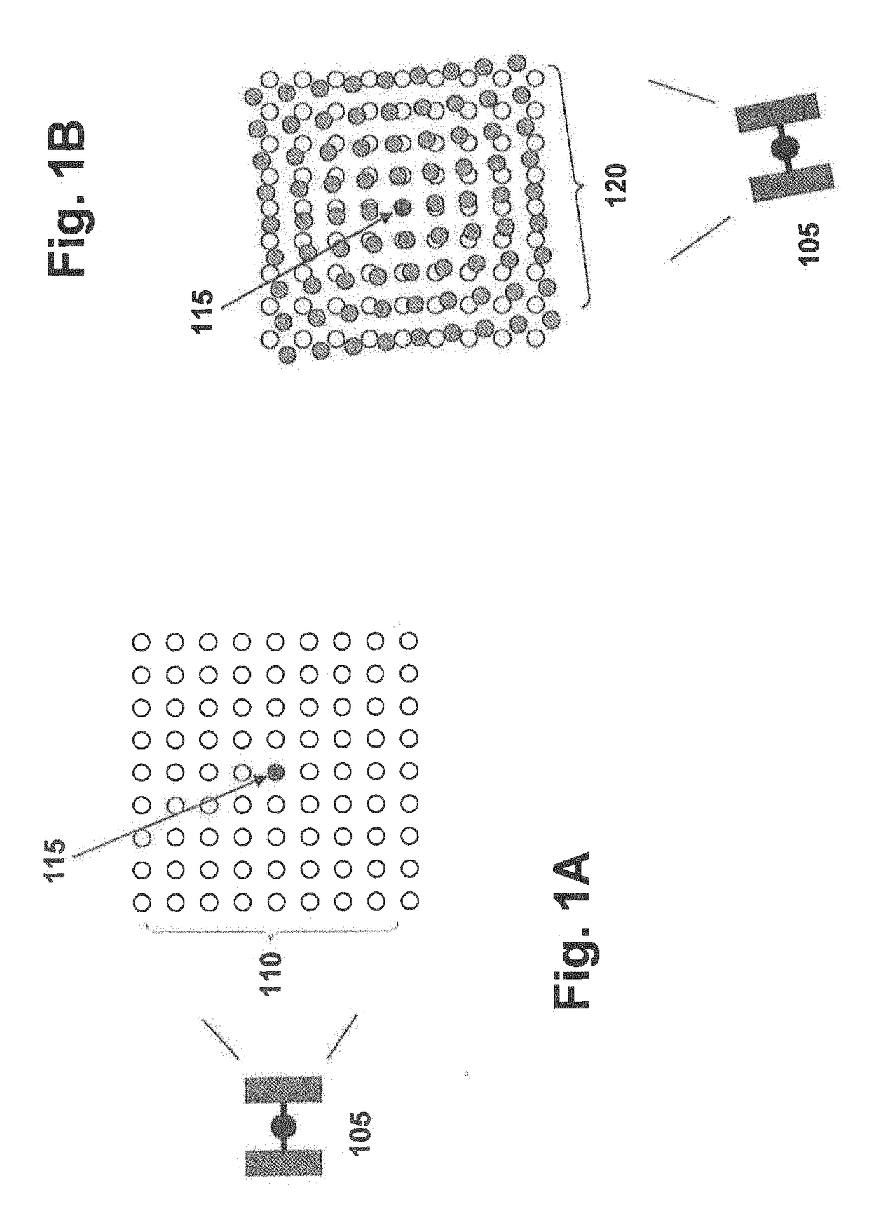
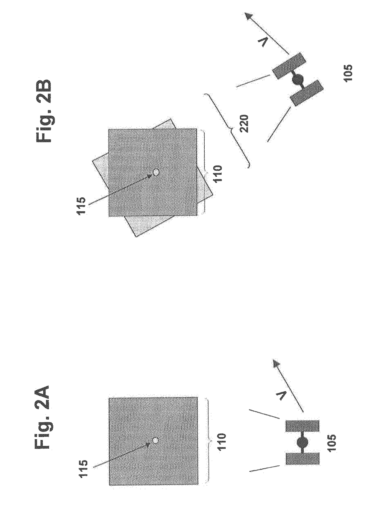
U.S. GOVERNMENT INTEREST[0001]There is no U.S. Government ownership or other interest in the invention(s) described and claimed herein.BACKGROUND[0002]This application generally relates to image processing, and more particularly, correcting frame-to-frame image changes due to platform motion for persistent observations.[0003]There is a desire to collect persistent video (i.e., multiple image sequences) of a target from overhead platform-based (e.g., airborne or space-based) sensors that can easily be viewed, and / or interpreted, via displays. This may be especially important for military personnel and / or for other persons, using portable devices that may have limited processing capabilities. Conventional persistent video sensors generally stay fixed to (or focus on) a single point, for instance, on the ground, while the overhead platform is in motion. The motion of the platform, however, causes changes in scale, perspective (e.g. parallax), rotation, and / or other changes in viewing g...

Claims


Application Information

Patent Timeline
IPC IPC(8): H04N5/232H04N5/33H04N5/235H04N5/445
CPCH04N5/23267H04N5/332H04N5/23254H04N5/2353H04N5/44504H04N5/144H04N5/145H04N23/45H04N23/6811H04N23/683G06T7/20H04N23/73H04N23/11
Inventor ROBINSON, IAN S.BLOOMER, JOHN D.
Owner RAYTHEON CO
Learn More