Metal wire manufacturing method and metal wire isolating method

A manufacturing method and metal wire technology, which is applied in semiconductor/solid-state device manufacturing, electrical components, circuits, etc., can solve problems affecting computing speed and large parasitic capacitance, so as to increase computing speed, improve parasitic capacitance, and reduce etching rate Effect

Inactive Publication Date: 2018-04-13
CHANGXIN MEMORY TECH INC
View PDF6 Cites 4 Cited by
  • Summary
  • Abstract
  • Description
  • Claims
  • Application Information

AI Technical Summary

Problems solved by technology

In the theoretical capacitance value formula, the thickness (dx) of the insulating medium is inversely proportional to the capacitance, and the dielectric coefficient of the insulating medium is proportional to the capacitance. When the manufacturing process shrinks, the space between the metal lines becomes smaller and smaller, and the insulating medium is completely When filling the groove between the two metal lines, the parasitic capacitance will become larger and larger, which will affect the operation speed

Method used


Image

  • Metal wire manufacturing method and metal wire isolating method
  • Metal wire manufacturing method and metal wire isolating method
  • Metal wire manufacturing method and metal wire isolating method

Examples


Embodiment 1

[0058] Such as Figure 8 ~ Figure 13 As shown, this embodiment provides a metal wire manufacturing method, the manufacturing method comprising:

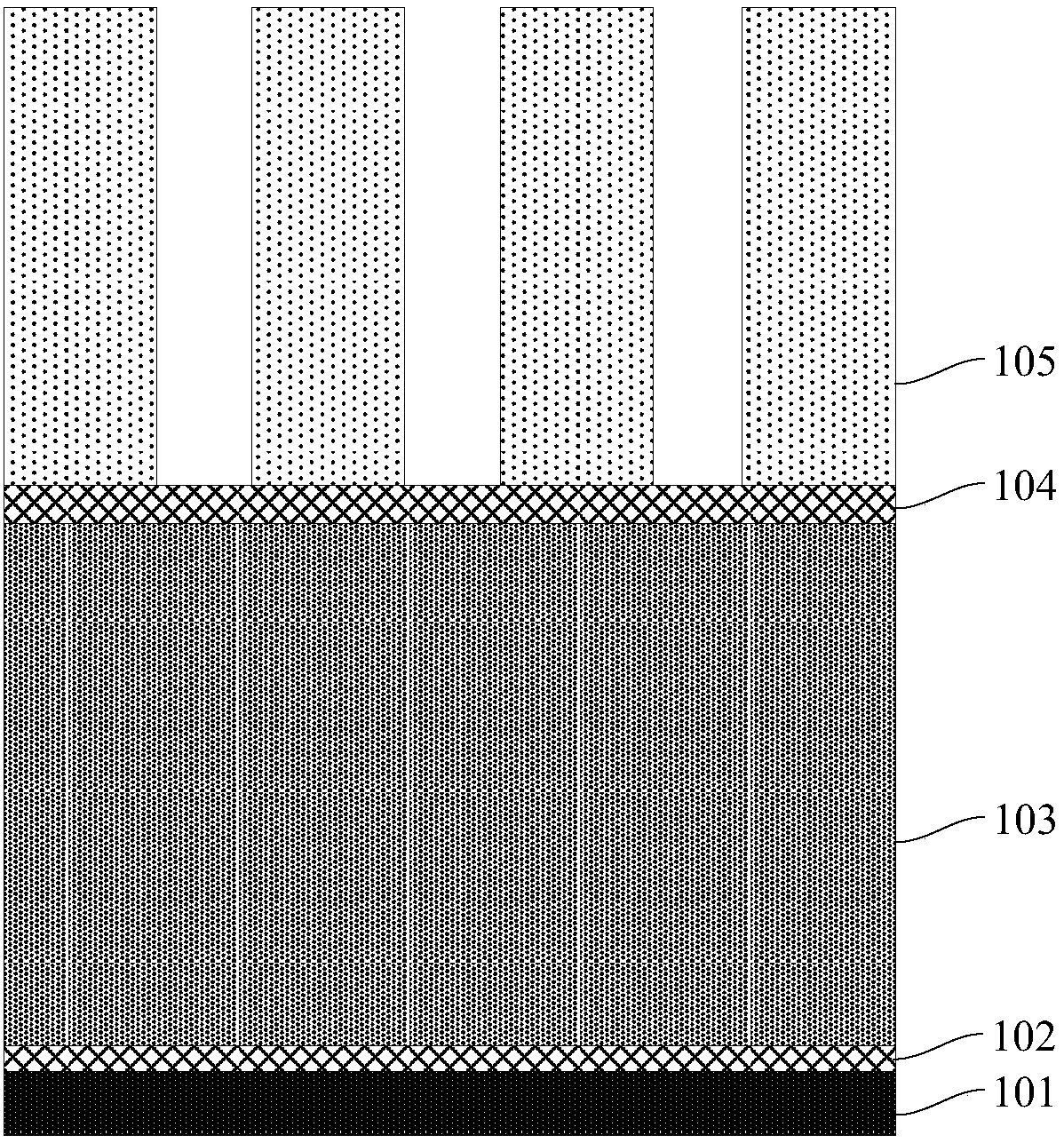
[0059] Such as Figure 8 As shown, step 1) is first performed to provide a substrate 201, which can be a silicon substrate, silicon oxide, or the like.

[0060] A titanium nitride (TiN) layer 202 is formed on the surface of the substrate 201 by a sputtering process, an evaporation process or a chemical vapor deposition process, and the titanium nitride (TiN) layer 202 can improve the connection between the subsequent metal layer 203 and the substrate. Adhesive strength of 201.

[0061] Then, a metal layer 203 is formed on the surface of the titanium nitride (TiN) layer 202 by using a sputtering process and an electroplating process, and the material of the metal layer 203 is selected from one of aluminum (Al) and aluminum-copper alloy (AlCu). A species, wherein, in the aluminum-copper alloy (AlCu), the mass ratio of copper (Cu) el...

Embodiment 2

[0073] Such as Figure 8 ~ Figure 14 As shown, the present embodiment provides a method for isolating metal lines, the method comprising:

[0074] Such as Figure 8 As shown, step 1) is first performed to provide a substrate 201, which can be a silicon substrate, silicon oxide, or the like.

[0075] A titanium nitride (TiN) layer 202 is formed on the surface of the substrate 201 by a sputtering process, an evaporation process or a chemical vapor deposition process, and the titanium nitride (TiN) layer 202 can improve the connection between the subsequent metal layer 203 and the substrate. Adhesive strength of 201.

[0076] Then, a metal layer 203 is formed on the surface of the titanium nitride (TiN) layer 202 by using a sputtering process and an electroplating process, and the material of the metal layer 203 is selected from one of aluminum (Al) and aluminum-copper alloy (AlCu). A species, wherein, in the aluminum-copper alloy (AlCu), the mass ratio of copper (Cu) element to...


PUM

PropertyMeasurementUnit
thicknessaaaaaaaaaa
thicknessaaaaaaaaaa
thicknessaaaaaaaaaa

Abstract

The invention provides a metal wire manufacturing method and a metal wire isolating method. The method comprises the steps that 1) an anti-reflection layer is formed on a metal layer; 2) a photoresistlayer is formed on the anti-reflection layer, and an etching window is formed in the photoresist layer; and 3) a halogen-containing gas is used and an alkane-based gas is added to etch the metal layer to separate the metal layer into a number of metal lines. The alkane-based gas reacts with the halogen-containing gas to generate an auxiliary carbon halogen compound, so as to avoid the side etching of the sidewall of the metal lines and reduce the consumption rate of the photoresist layer during the etching process. According to the invention, the added alkane-based gas is used as the source of an etching aluminum by-product CClx, which can effectively reduce the etching rate of the photoresist layer; reduced line width of the metal lines and top damage, which are caused by insufficient residue of the photoresist layer, are avoided; side etching of the sidewall of the metal lines is avoided through the by-product CClx; and the overall width of the metal lines is the same as the targetwidth.

Description

technical field [0001] The invention belongs to the field of semiconductor manufacturing, and in particular relates to a method for manufacturing metal wires and a method for isolating metal wires. Background technique [0002] An existing metal line etching process flow such as Figure 1 ~ Figure 2 As shown, generally, the structure of the metal line before etching is as figure 1 As shown, it includes a substrate 101, a titanium nitride (TiN) layer 102 on the substrate 101, a metal layer 103 on the titanium nitride (TiN) layer 102, and an anti-reflection layer on the metal layer 103 104 and a photoresist layer 105 on the antireflection layer 104 . Then by using a halogen-containing gas, such as Cl 2 、BCl 3 , HCl, HBr and other gases, at a certain chamber temperature, usually 50-70 degrees Celsius, chamber pressure 4mTorr-20mTorr, etching time is about 2 minutes to 4 minutes, can etch a complete metal wire, such as aluminum ( Al) reacts with Cl ions in the etching gas t...

Claims


Application Information

Patent Timeline
Patent Type & Authority Applications(China)
IPC IPC(8): H01L21/3065H01L21/768
CPCH01L21/3065H01L21/30655H01L21/76853
Inventor 不公告发明人
Owner CHANGXIN MEMORY TECH INC
Why Eureka
Try Eureka