Method and system for boost pressure control

Active Publication Date: 2017-11-23
FORD GLOBAL TECH LLC
View PDF0 Cites 8 Cited by
  • Summary
  • Abstract
  • Description
  • Claims
  • Application Information

AI Technical Summary

Benefits of technology

[0002]Engines may be operated using boosting devices, such as turbochargers or superchargers, to increase mass airflow into a combustion chamber. Turbochargers and superchargers co

Problems solved by technology

However, the inventors herein have recognized potential issues with such systems.
As one example, the regulation of turbocharger boost pressure and turbocharger speed by wastegate actuation may be slow, resulting in boost errors.
However, due to the relatively slow turbocharger dynamics of the wastegate, the desired boost pressure may decrease faster than the compressor can be decelerated.
Consequently, while the turbine is decelerating, a boost pressure downstream of the compressor may exceed a desired

Method used


Image

  • Method and system for boost pressure control
  • Method and system for boost pressure control
  • Method and system for boost pressure control

Examples


Embodiment Construction

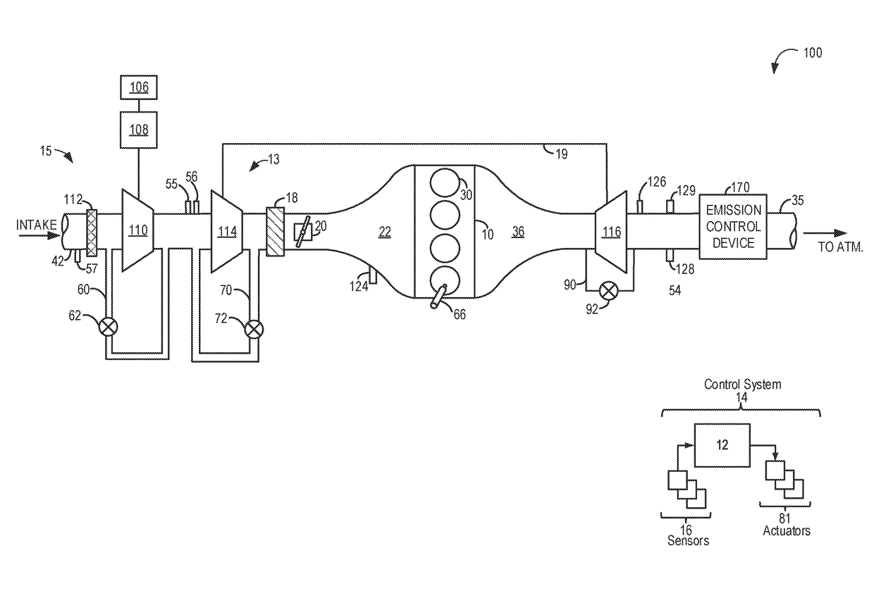
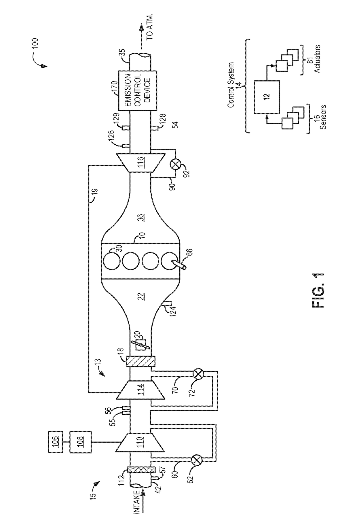
[0014]The following description relates to systems and methods for improving boost control in an engine system having staged boosting devices, such as in the boosted engine system of

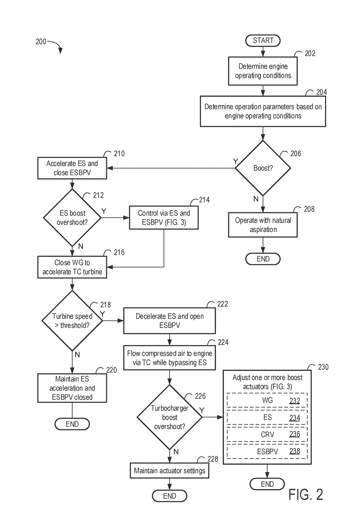
[0015]FIG. 1, wherein a turbocharger is staged downstream of an electric supercharger. A controller may be configured to perform a routine, such as the example routines of FIGS. 2-3, to use the electric supercharger to reduce turbo lag while regulating boost pressure overshoot using adjustments to a rotation speed of the supercharger motor and the opening of a bypass valve coupled across the supercharger. These adjustments may be used in a complementary frequency to boost pressure controlling wastegate valve adjustments. During conditions of boost pressure overshoot downstream of the turbocharger, the electric supercharger compressor speed may be controlled to choke airflow through the turbocharger, the supercharger speed adjusted based on a compressor map, such as the map of FIG. 4. An example boost con...


PUM


Abstract

Methods and systems are provided for controlling boost pressure in a staged engine system comprising a turbocharger and an upstream electric supercharger. In one example, a method may include accelerating an electric supercharger to choke the flow of air to the engine in the event of turbocharger overboost.

Description

FIELD[0001]The present description relates generally to methods and systems for regulating engine boost pressure in staged boosted engine systems.BACKGROUND / SUMMARY[0002]Engines may be operated using boosting devices, such as turbochargers or superchargers, to increase mass airflow into a combustion chamber. Turbochargers and superchargers compress intake air entering the engine using an intake compressor. Further, one or more intake charging devices may be staged in series or parallel to improve engine boost response.[0003]One example of a multi-staged boosted engine is shown by Stewart et al. in U.S. Pat. 7,958,730. Therein, a multistage series turbocharger apparatus contains a low pressure turbocharger and a high pressure turbocharger, coordinated to maintain at least one operating parameter by adjusting turbocharger speeds. The low pressure turbocharger allows for quick acceleration to compensate for the slow acceleration of the high pressure turbocharger, also known as turbo la...

Claims


Application Information

Patent Timeline
IPC IPC(8): F02B37/04F02B37/18
CPCF02B37/04F02B37/18F02D41/0007F02B37/14F02B2039/168F02B39/10F02B37/16F02B2037/122F02B37/127F02B37/162F02B37/12F02B37/183F02D23/00F02D2200/602F02D2200/0406Y02T10/12
Inventor XIAO, BAITAOOSSAREH, HAMID-REZABANKER, ADAM NATHAN
Owner FORD GLOBAL TECH LLC
Why Eureka
Try Eureka