Vehicle position determination device, vehicle control system, vehicle position determination method, and vehicle position determination program product

a technology for vehicle position determination and vehicle control system, which is applied in vehicle position/course/altitude control, process and machine control, instruments, etc., can solve the problem of inability to accurately determine the position of a vehicle, and achieve the effect of determining the position of the vehicle more accurately

Active Publication Date: 2017-11-23
HONDA MOTOR CO LTD
View PDF0 Cites 30 Cited by
  • Summary
  • Abstract
  • Description
  • Claims
  • Application Information

AI Technical Summary

Benefits of technology

[0021]According to the invention described in each aspect, it is possible to determine the position of the vehicle more accurately.

Problems solved by technology

However, according to the related art, a position of a vehicle may not be able to be accurately determined in some cases.

Method used


Image

  • Vehicle position determination device, vehicle control system, vehicle position determination method, and vehicle position determination program product
  • Vehicle position determination device, vehicle control system, vehicle position determination method, and vehicle position determination program product
  • Vehicle position determination device, vehicle control system, vehicle position determination method, and vehicle position determination program product

Examples


first embodiment

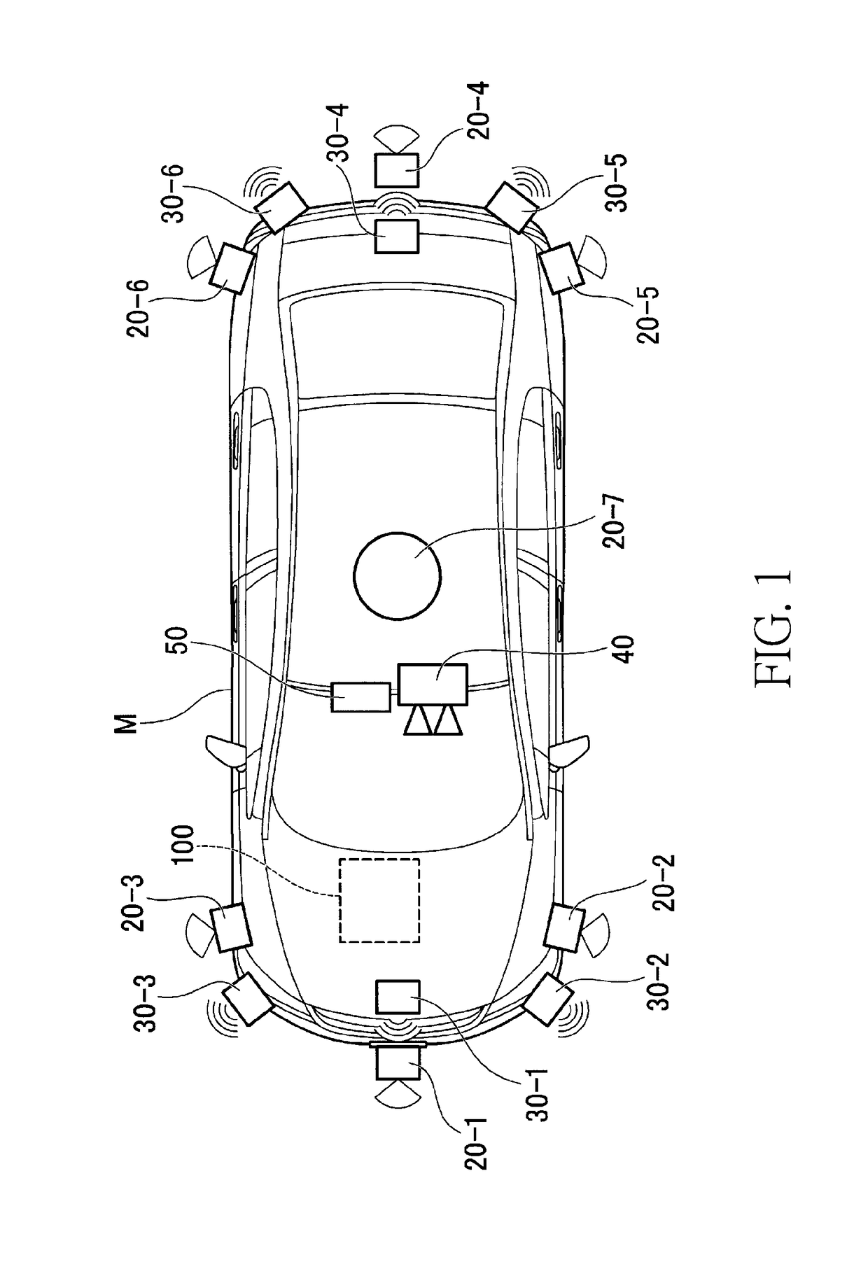
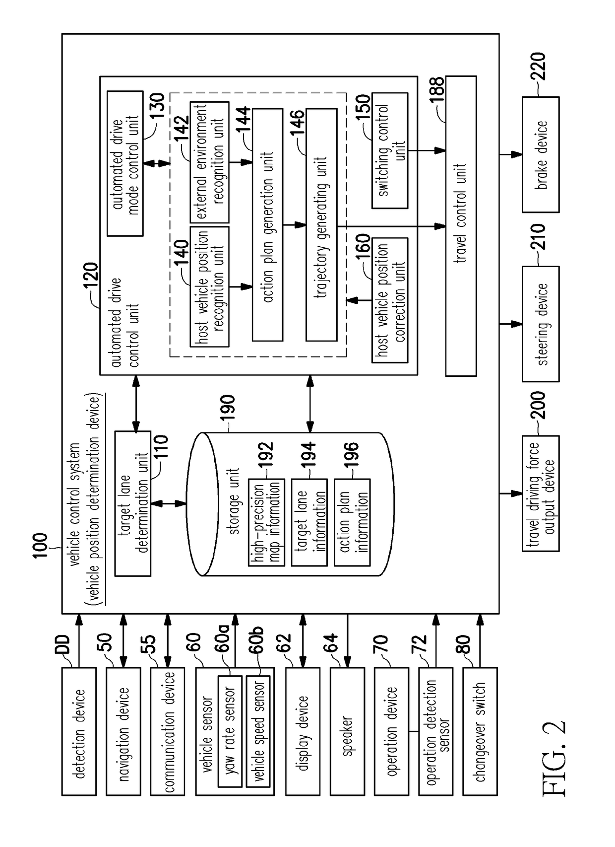
[0052]FIG. 2 is a functional configuration diagram focusing on the vehicle control system 100 according to a first embodiment. A detection device DD including a finder 20, a radar 30, a camera 40, or the like, a navigation device 50, a communication device 55, a vehicle sensor 60, a display device 62, a speaker 64, an operation device 70, an operation detection sensor 72, a changeover switch 80, a vehicle control system 100, a travel driving force output device 200, a steering device 210, and a brake device 220 are mounted on a host vehicle M. These apparatuses or devices are connected to each other by a multiplex communication line such as a controller area network (CAN) communication line, a serial communication line, a wireless communication network, or the like. A vehicle control system in the claims does not indicate only the “vehicle control system 100” and may include a configuration (for example, the detection device DD) other than the vehicle control system 100.

[0053]The na...

second embodiment

[0158]Hereinafter, a second embodiment will be described. The second embodiment differs from the first embodiment in that various proportional gains K in the host vehicle position correction unit 160 are changed on the basis of a position measurement error of the position derived by the GNSS receiver of the navigation device 50. Hereinafter, the differences will be mainly described.

[0159]For example, the navigation device 50 may derive the position measurement error on the basis of a pseudo distance obtained when the position of the host vehicle M is obtained, and an accuracy reduction rate (Dilution Of Precision: DOP). The pseudo distance is, for example, a distance obtained by treating an arrival time of radio waves transmitted from an artificial satellite as a propagation time and multiplying the propagation time by a speed of light. Further, the accuracy reduction rate is an index indicating a degree of influence on position measurement accuracy due to an arrangement of the arti...

third embodiment

[0165]Hereinafter, a third embodiment will be described. FIG. 21 is a functional configuration diagram focusing on a vehicle control system 100A according to the third embodiment. In the third embodiment, for example, a detection device DD, a navigation device 50, a vehicle sensor 60, a display device 62, and a vehicle control system 100A are mounted on a host vehicle M, similar to the first and second embodiments described above. The vehicle control system 100A in the third embodiment includes, for example, a target lane determination unit 110, a host vehicle position recognition unit 140, an external environment recognition unit 142, and a host vehicle position correction unit 160. The vehicle control system 100A in the third embodiment may be applied, as an application, to an existing navigation system, may be applied to a driving support device, or may be applied to an automated driving device, such as the vehicle control system 100 illustrated in the first and second embodiment...


PUM


Abstract

An object is to provide a vehicle position determination device, a vehicle control system, a vehicle position determination method, and a vehicle position determination program capable of determining a position of a vehicle with higher accuracy. A vehicle position determination device includes a coordinates acquisition unit that acquires a position of a vehicle in a geographic coordinate system, a recognition unit that acquires lane information of a road on which the vehicle travels and recognizes the position of the vehicle on the lane, and a control unit that corrects the position acquired by the coordinates acquisition unit on the basis of the position recognized by the recognition unit, and determines the position of the vehicle in the geographic coordinate system.

Description

CROSS-REFERENCE TO RELATED APPLICATION[0001]This application claims the priority benefit of Japan application serial no. 2016-102430, filed on May 23, 2016. The entirety of the above-mentioned patent application is hereby incorporated by reference herein and made a part of this specification.BACKGROUND OF THE INVENTIONField of the Invention[0002]The present invention relates to a vehicle position determination device, a vehicle control system, a vehicle position determination method, and a vehicle position determination program product.Description of Related Art[0003]In the related art, a technology for allowing a position of a vehicle to be recognized with a position measurement system using satellites such as a global positioning system (GPS), imaging white lines on a road being traveled on, and recognizing a relative position of the vehicle relative to dividing lines of the road being traveled on the basis of a captured image is known (for example, see Japanese Unexamined Patent ...

Claims


Application Information

Patent Timeline
Patent Type & Authority Applications(United States)
IPC IPC(8): G01S19/40G06K9/00
CPCG06K9/00798G01S19/40G01S19/51G05D1/0061G05D1/0212G05D1/0251G05D1/0257G05D1/027G05D1/0274G05D1/0278G05D1/0289G05D2201/0213G01S19/485G01C21/28G06V20/588
Inventor HOSOYA, TOMOYUKIMORI, YOSHIHIRO
Owner HONDA MOTOR CO LTD
Why Eureka
Try Eureka