Woled display device

a display device and display screen technology, applied in semiconductor devices, diodes, electrical devices, etc., can solve the problems of poor woled display devices cannot better filter the white light emitted by the white light emitting layer, and the effect of blue light and green light is poor, so as to achieve a wide color gamut

Inactive Publication Date: 2017-11-23
TCL CHINA STAR OPTOELECTRONICS TECH CO LTD
View PDF9 Cites 3 Cited by
  • Summary
  • Abstract
  • Description
  • Claims
  • Application Information

AI Technical Summary

Benefits of technology

[0005]An objective of the present invention is to provide a WOLED display device, in which a light purification layer with a specific absorption wavelength is provided to raise the light filtering effect of the color filter layer, and the light purities of the red, green, blue, three primary colors are high to show a wider color gamut.
[0027]The benefits of the present invention are: the present invention provides a WOLED display device, comprising a substrate, a TFT array layer located on the substrate, a light purification layer located on the TFT array layer, a color filter layer located on the light purification layer and a WOLED located on the color filter layer; wherein the red, green, blue light resist units of the color filter layer filtrate white light emitted by the WOLED to respectively form red, green, blue lights, and the light purification layer selectively absorbs the red, green, blue lights to decrease half band widths of the red, green, blue lights to promote the light filtering effect of the color filter layer, and the light purities of the red, green, blue, three primary colors are high to show a wider color gamut.

Problems solved by technology

The red, green, blue color resist layers of the color filter cannot better filtrate the white light emitted by the white light emitting layer.
The existence of the peaks makes that the effects of and blue light and the green light are poor after the white light source emitted by the WOLED passes through the color filter layer.
Therefore, the WOLED display device has drawbacks that the lighting purities of the red, green, blue, three primary colors are relatively low, and the color gamut is narrow.

Method used


Image

  • Woled display device
  • Woled display device
  • Woled display device

Examples


Embodiment Construction

[0035]For better explaining the technical solution and the effect of the present invention, the present invention will be further described in detail with the accompanying drawings and the specific embodiments.

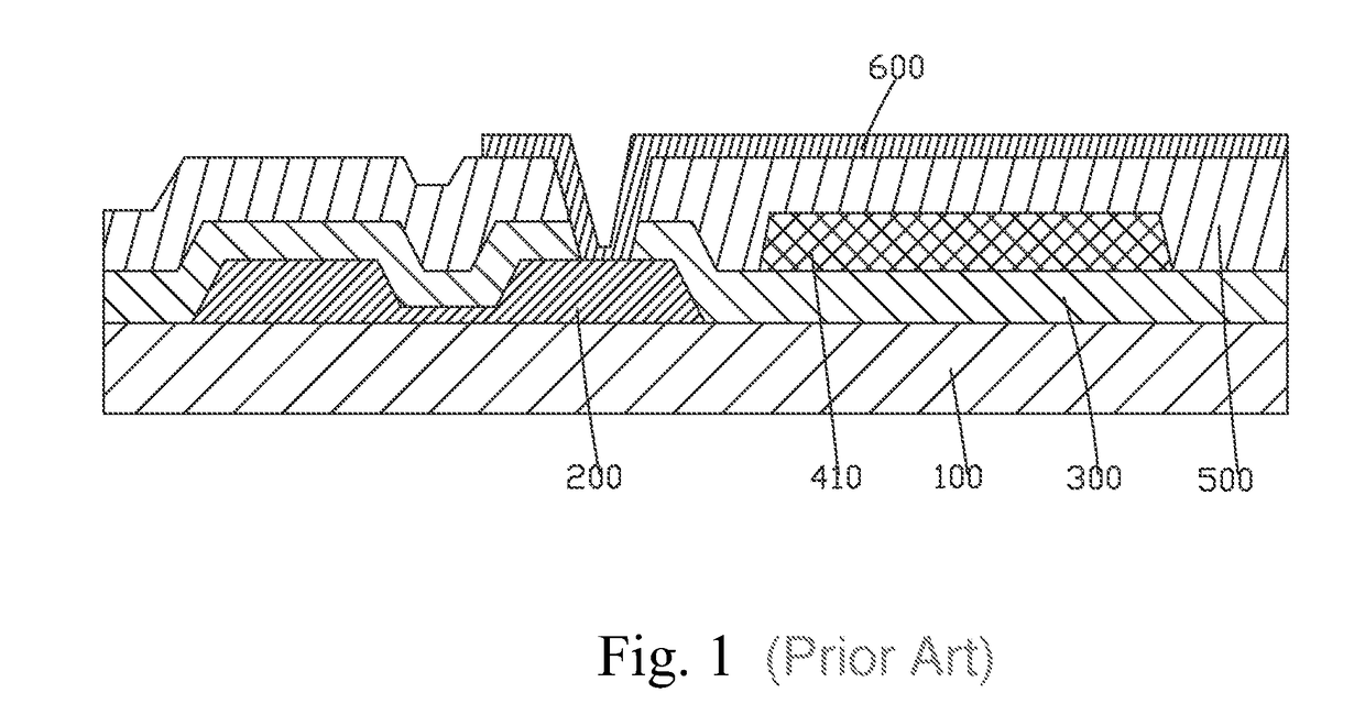
[0036]Please refer to FIG. 4. The present invention provides a WOLED display device, comprising a substrate 10, a TFT array layer 20 located on the substrate 10, a light purification layer 60 located on the TFT array layer 20, a color filter layer 40 located on the light purification layer 60 and a WOLED 30 located on the color filter layer 40.

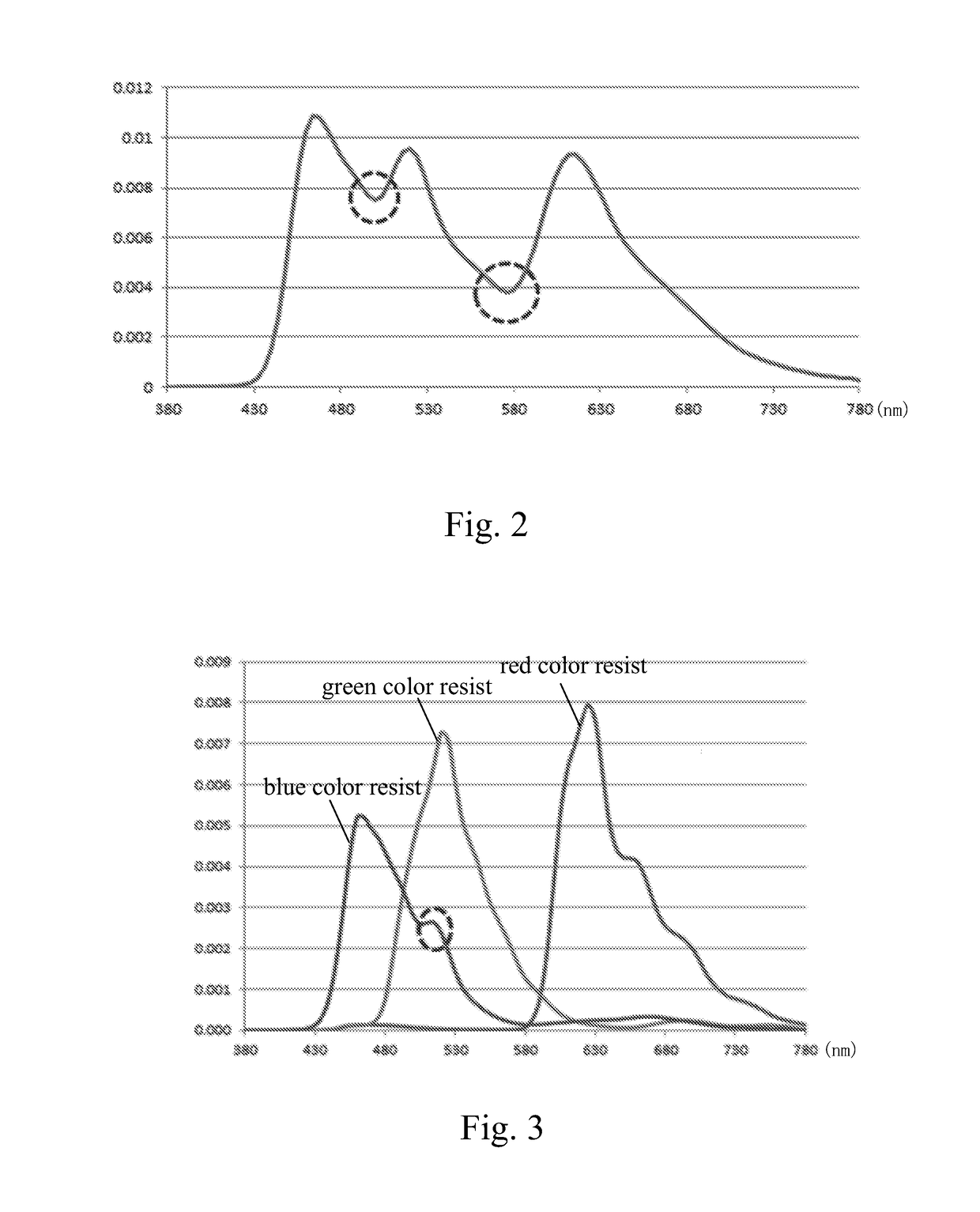
[0037]Specifically, the color filter layer 40 comprises a plurality of red, green, blue light resist units 41, 42, 43 which are aligned in array.

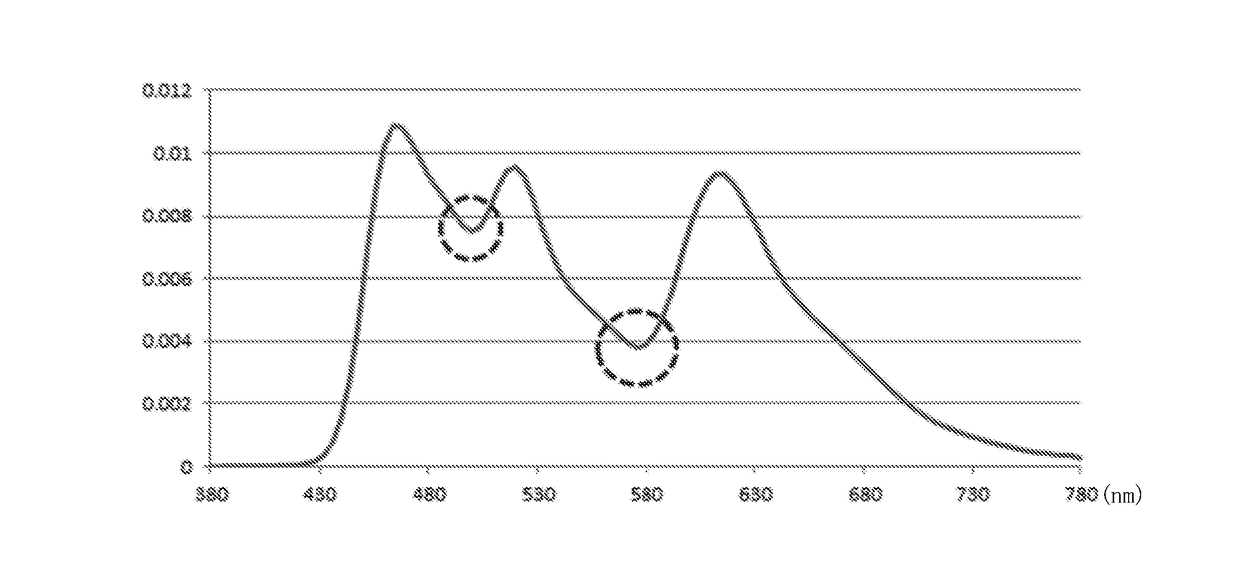
[0038]Specifically, the red, green, blue light resist units 41, 42, 43 of the color filter layer 40 filtrate white light emitted by the WOLED 30 to respectively form red, green, blue lights, and the light purification layer 60 selectively absorbs the red, green, blue lights to decrease half band...


PUM


Abstract

Disclosed is a WOLED display device, including a substrate (10), a TFT array layer (20) located on the substrate (10), a light purification layer (60) located on the TFT array layer (20), a color filter layer (40) located on the light purification layer (60) and a WOLED (30) located on the color filter layer (40). The color filter layer (40) includes red, green, blue light resist units (41, 42, 43) which are aligned in array. The red, green, blue light resist units (41, 42, 43) filtrate white light to respectively form red, green, blue light, and the light purification layer (60) selectively absorbs the red, green, blue light to decrease half band widths thereof to promote the light filtering effect of the color filter layer (40), and light purity of the three primary colors of red, green, and blue are high to show a wider color gamut.

Description

FIELD OF THE INVENTION[0001]The present invention relates to a flat panel display field, and more particularly to a WOLED display device.BACKGROUND OF THE INVENTION[0002]The active matrix panel display elements possess many merits of thin frame, power saving, no radiation, etc. and have been widely used. The Organic Light Emitting Diode (OLED) display technology is a flat panel display technology which has great prospects for development. It possesses extremely excellent display performance, and particularly the properties of self-illumination, simple structure, ultra thin, fast response speed, wide view angle, low power consumption and capability of realizing flexible display, and therefore is considered as the “dream display”. Meanwhile, the investment for the production equipments is far smaller than the Thin Film Transistor-Liquid Crystal Display (TFT-LCD). It has been favored by respective big display makers and has become the main selection of the third generation display elem...

Claims


Application Information

Patent Timeline
Patent Type & Authority Applications(United States)
IPC IPC(8): H01L27/32H01L51/52
CPCH01L27/3213H01L51/5237H01L27/322H01L27/3248H10K59/38
Inventor LIU, HONGLEE, YUNGJUICHEN, HSIAOHSIEN
Owner TCL CHINA STAR OPTOELECTRONICS TECH CO LTD
Why Eureka
Try Eureka