High-speed permanent magnetic motor assembly

a permanent magnetic motor and assembly technology, applied in the direction of bearing cooling, mechanical equipment, mechanical energy handling, etc., can solve the problems of reducing the efficiency of the motor, the motor housing cannot effectively cool the stator of the motor, and the rotor cannot be used, so as to improve the bearing capacity of the assembly, improve the bearing capacity, and reduce the viscosity coefficient.

Inactive Publication Date: 2017-11-23
HANGZHOU WANCHEN ELECTROMECHANICAL TECH CO LTD
View PDF9 Cites 8 Cited by
  • Summary
  • Abstract
  • Description
  • Claims
  • Application Information

AI Technical Summary

Benefits of technology

[0017]A liquid phase of the low-viscous two-phase fluid has a low viscosity coefficient, to penetrate through a porous bushing, during which a part of the liquid is vaporized due to pressure reduction from the resistance of the porous media, and a part of the liquid arrives at a clearance between each of the bearings and the rotor. The liquid of the low-viscous two-phase fluid is vaporized during discharge, along an axial direction from the bearing to increase the vapor in the clearance, improve a bearing capacity of the assembly, retain position accuracy of an aerostatic bearing. The liquid in the low-viscous

Problems solved by technology

A traditional manner of adding a water jacket outside a motor housing can hardly cool a stator of the motor effectively, and is of no use in cooling the rotor.
An air cooling manner requires an increase in clearance between a stator and a rotor and allows an increase in ventilation volume, which not only reduces efficiency of a motor, but also increases power consumption of ventilation.
Often, high rotation speeds make a challenge for bearings: a common oil journal bearing is subjected to a sharp increase in losses with an increase in rotation speed; a ball bearing is limited by a rotation speed; although there is no friction loss, a magnetic bearing is subjected to substantial axis fluctuation

Method used


Image

  • High-speed permanent magnetic motor assembly
  • High-speed permanent magnetic motor assembly
  • High-speed permanent magnetic motor assembly

Examples


Embodiment Construction

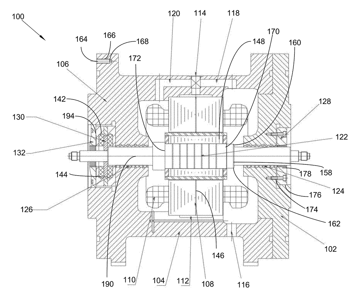
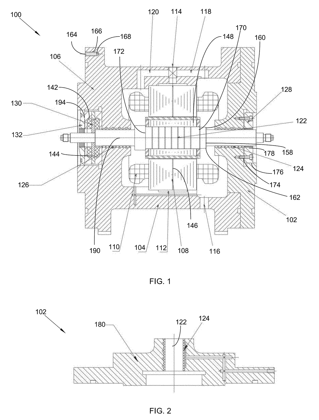
[0043]The following detailed description is merely exemplary in nature and is not intended to limit the described embodiments or the application and uses of the described embodiments. As used herein, the word “exemplary” or “illustrative” means “serving as an example, instance, or illustration.” Any implementation described herein as “exemplary” or “illustrative” is not necessarily to be construed as preferred or advantageous over other implementations. All of the implementations described below are exemplary implementations provided to enable persons skilled in the art to make or use the embodiments of the disclosure and are not intended to limit the scope of the disclosure, which is defined by the claims. For purposes of description herein, the terms “upper,”“lower,”“left,”“rear,”“right,”“front,”“vertical,”“horizontal,” and derivatives thereof shall relate to the invention as oriented in FIG. 1. Furthermore, there is no intention to be bound by any expressed or implied theory pres...


PUM


Abstract

A high-speed permanent magnetic motor assembly generates a magnetic field to produce mechanical output power. The assembly comprises a motor, a motor housing, and a radial bearing block. A motor housing supports a rotor and the radial bearing block with a left radial aerostatic bearing, a right aerostatic bearing, and an axial thrust aerostatic bearing. The bearings are porous aerostatic bearings that use a low-viscous vapor-liquid two-phase fluid as a lubricant, which penetrates through a porous bushing. The liquid vaporizes from pressure reduction, and part of the liquid arrives at a clearance between each of the bearings and the rotor. The liquid of the two-phase fluid is vaporized during discharge along an axial direction from the bearing. This increases the vapor in the clearance, improve a bearing capacity, retain position accuracy of an aerostatic bearing, and cool the aerostatic bearings and the rotor.

Description

CROSS REFERENCE OF RELATED APPLICATIONS[0001]This application claims the benefits of Chinese application no. 201610349341.9, filed May 23, 2016 and is titled the same.FIELD OF THE INVENTION[0002]The present invention relates generally to a high-speed permanent magnetic motor assembly. More so, the present invention relates to a magnetic motor assembly that produces mechanical output power, has a self-cooling function as well as high rotation accuracy; whereby the assembly comprises a motor, a motor housing, and a radial bearing block; whereby the rotor is supported on the motor housing and the radial bearing block with a left radial aerostatic bearing, a right aerostatic bearing, and an axial thrust aerostatic bearing; whereby the left radial aerostatic bearing, the right aerostatic bearing, and the axial thrust aerostatic bearing are porous aerostatic bearings using a low-viscous vapor-liquid two-phase fluid as a lubricant.BACKGROUND OF THE INVENTION[0003]The following background i...

Claims


Application Information

Patent Timeline
IPC IPC(8): H02K7/09F16C32/06F16C37/00
CPCH02K7/09F16C32/0696F16C2380/26F16C37/002F16C32/0625F16C32/0607F16C32/0662H02K5/04H02K5/10H02K5/161H02K5/20H02K9/20H02K5/1672H02K7/1838H02K2205/03Y02E10/72
Inventor GU, FAHUAYUAN, PENGSONG, JIEJIEJI, WEIXING
Owner HANGZHOU WANCHEN ELECTROMECHANICAL TECH CO LTD
Why Eureka
Try Eureka