Device and method for fixing a relative geometric position of an eye

a technology of relative geometric position and fixing device, which is applied in the field of devices for fixing relative geometric position of eyes, can solve the problems of heavy bleeding in the conjunctiva, risk of suction loss, unpleasant and disruptive for patients and physicians, etc., and achieves the effect of preventing the closure and facilitating the tensioning of the clamping mechanism

Inactive Publication Date: 2017-11-30
CARL ZEISS MEDITEC AG
View PDF0 Cites 1 Cited by
  • Summary
  • Abstract
  • Description
  • Claims
  • Application Information

AI Technical Summary

Benefits of technology

[0027]A device containing a clamping mechanism with two mutually tensible straps that are connected to one another via a spring coupling embodies in turn a special design of the inventive device that makes especially easy a tensioning of the clamping mechanism with simultaneous control of the positioning of the container on the eye.
[0028]The frictionally engaged coupling of the container to the eye is produced in the inventive device by the clamping effect of the clamping mechanism, which is partly placed between the eyeball and the eyelid. In one especially advantageous embodiment of the inventive device the clamping mechanism has structure for blocking the eyelid. This is the case when the part of the clamping mechanism that is placed between the eyeball and the eyelid is designed such that it can grip over a predominant part of the width of an eye between the eyeball and the lid and thus hold back the entire lid in its width and prevent it from closing. The structure for blocking the lids can in the process be realized either by having the straps of the clamping mechanism themselves correspondingly molded or can contain a special attachment.

Problems solved by technology

However, suctioning a patient interface on the eye with a vacuum involves both technical and medical disadvantages: vigorous suctioning, which is necessary for solutions known thus far, in order to actually keep the eye still, sometimes causes heavy bleeding in the conjunctiva.
While these injuries heal within a couple of days, both patients and physicians find them to be unpleasant and disruptive.
In addition, with vacuum suctioning there is always the risk of a loss of suction, so-called “suction loss”, in which case the patient interface loosens from the eye during the laser procedure.
Under circumstances, this can cause serious injuries to the eye, in particular when the laser beam is not disconnected or blocked in time.
Not least, the suctioning of a patient interface on the eye by a vacuum complicates the procedure as well as the system: To generate the vacuum, in particular in the case of laser-supported surgical procedures, in which a manual generation of a vacuum would be too risky, a pump must be integrated into the system and a hose line installed to the patient interface.
This increases production costs of the therapy system and a hose connection can also hamper the handling of the therapy system during the operation.
However, such a device does not permit a secure fixation of the eye, since they do not enable the setting of a defined and reproducible contact pressure of the contact glass on the eye.
However, if such an eye speculum is supposed to be used for fixation of the eye in the sense of a fixing of its geometric position with respect to a diagnosis and / or therapy system, this can only occur through a corresponding pressure on the eye ball, which in turn would lead to an undesired high intraocular pressure.
However, due to the design of the patient interface and because the eye speculum can be seated anywhere, a reproducible pressing of the patient interface is difficult.

Method used


Image

  • Device and method for fixing a relative geometric position of an eye
  • Device and method for fixing a relative geometric position of an eye
  • Device and method for fixing a relative geometric position of an eye

Examples


second embodiment

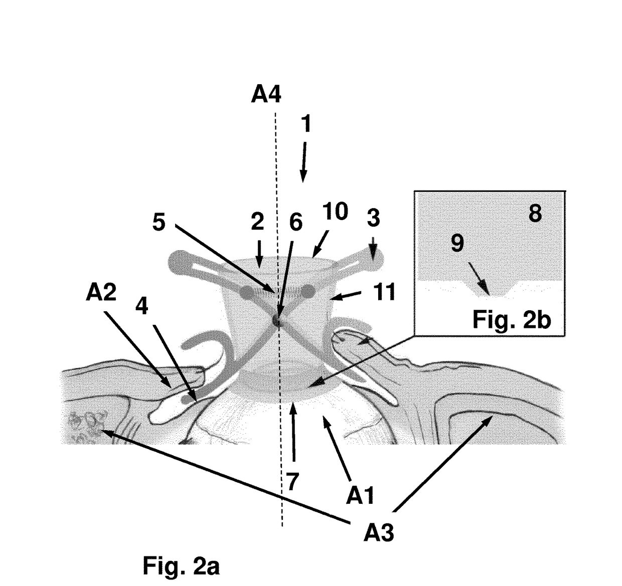
[0065]The eye contact surface 9 in the second embodiment does not contain any nubs or similar structures. In contrast, it is surface coated with a material that produces an additional adhesion effect between the container 2 and the eye A1. One example of this is a coating with a collagen or a hydrophilic material with adhesive effect that can absorb the tear fluids.

first embodiment

[0066]In the process, it is to be noted that the design of the eye contact surface 9 is independent from the refractive active material that is used, so that an inventive device 1 as described in the first embodiment can also contain an adhesion effective surface coating in place of the nub structure and vice versa. Also, a combination of a corresponding nub structure and a surface coating is possible.

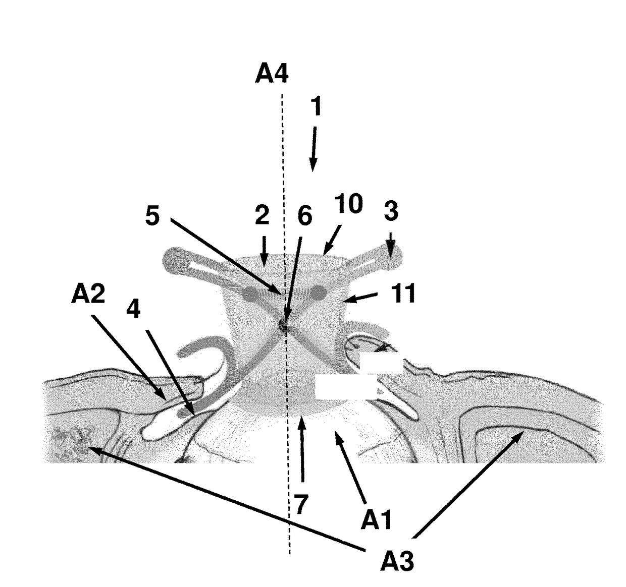
[0067]FIG. 4 shows a schematized comprehensive view of an embodiment of the inventive ophthalmological diagnosis and / or therapy system 100. We will not go into the details of such a diagnosis and / or therapy system 100. FIG. 4 only serves the purpose of using the example of a laser therapy system operating according to the LASIK method to show how an eye A1 is fixed on an ophthalmological diagnosis and / or therapy system by use of an inventive device 1 and thus the relative geometric position of an eye A1 is fixed to an ophthalmological diagnosis and / or therapy system 100. The laser ther...


PUM


Abstract

A device and a method for fixing a relative geometric position of an eye with respect to an ophthalmological diagnosis and/or therapy system. A device having a container with upper edge designed to produce a mechanically fixed connection between the container and the ophthalmological diagnosis and/or therapy system, and a lower edge which can be placed with a form fit onto the eye, and a clamping mechanism for producing a force-fit connection of the container to the eye, wherein the clamping mechanism has a movable connection to the container is a fixed rotation point or a fixed rotation axis in a jacket area of the container, and by a corresponding method.

Description

RELATED APPLICATIONS[0001]This application is a National Phase entry of PCT Application No. PCT / EP2015 / 078992 filed Dec. 8, 2015 which application claims the benefit of priority to German Application No. 10 2014 225 636.4, filed Dec. 11, 2014, the entire disclosures of which are incorporated herein by reference.FIELD OF THE INVENTION[0002]Embodiments of the present invention relate to a device for fixing a relative geometric position of an eye for an ophthalmological diagnosis and / or therapy system. The invention further relates to an ophthalmological diagnosis and / or therapy system with such a device as well as a method for fixing a relative geometric position of an eye for an ophthalmological diagnosis and / or therapy system.BACKGROUND[0003]Many examinations, therapies and in particular surgical interventions in ophthalmology are carried out with the assistance of partially or fully automated systems. Thus eye ailments are for example characterized by means of the corresponding dia...

Claims


Application Information

Patent Timeline
Patent Type & Authority Applications(United States)
IPC IPC(8): A61B3/107A61B3/10A61F9/009A61B3/00
CPCA61B3/107A61B3/0083A61F9/009A61B3/102A61B3/0008A61B3/125
Inventor RILL, MICHAEL STEFAN
Owner CARL ZEISS MEDITEC AG
Why Eureka
Try Eureka