
Apparatus and method for positioning, implanting and using a stimulation lead

a technology applied in the field of implanted electrodes and electrodes, can solve the problems of ineffective existing systems, time-consuming, inconvenient use, etc., and achieve the effects of reducing the number of implanted electrodes, and reducing the number of patients

Active Publication Date: 2017-11-30
SPR THERAPEUTICS
View PDF4 Cites 24 Cited by
  • Summary
  • Abstract
  • Description
  • Claims
  • Application Information

AI Technical Summary

Benefits of technology

The patent text describes a needle assembly used in a medical procedure that allows for better therapeutic effects. The needle assembly includes an outer sheath and a movable inner stylet that can be repositioned before the anchor is deployed to maximize the treatment.

Problems solved by technology

As described extensively in the literature, the existing systems and devices for peripheral nerve stimulation may not meet the needs of the clinicians and patients.
Existing systems can be inefficient; time consuming; and too invasive.
They may also require prohibitively extensive training and skill to use; exhibit (or contribute to) poor device performance / failure and suboptimal efficacy / effectiveness / safety; and prohibit use in patients and clinical settings that could benefit from electrical stimulation.
These systems, with two separate steps, may be inefficient, time consuming, and not ideal for patients as this may require two separate needle insertions.
Owing to the relatively fragile nature of the lead itself, the ability to adjust the positioning of the lead—even small amounts—is quite limited.
The tines / sutures secure the lead in its desired location, but repositioning of the lead during the insertion process is difficult, if not impossible, owing to the lead's positioning in the needle and the non-conductive nature of its tines / sutures.
Further, movement or removal of the lead after it is deployed will cause tissue damage and disruption.

Method used


Image

  • Apparatus and method for positioning, implanting and using a stimulation lead
  • Apparatus and method for positioning, implanting and using a stimulation lead
  • Apparatus and method for positioning, implanting and using a stimulation lead

Examples


Embodiment Construction

[0171]Reference will now be made in detail to exemplary embodiments of the present invention, examples of which are illustrated in the accompanying drawings. It is to be understood that other embodiments may be utilized and structural and functional changes may be made without departing from the respective scope of the invention. Moreover, features of the various embodiments may be combined or altered without departing from the scope of the invention. As such, the following description is presented by way of illustration only and should not limit in any way the various alternatives and modifications that may be made to the illustrated embodiments and still be within the spirit and scope of the invention.

[0172]Any elements described herein as singular can be pluralized (i.e., anything described as “one” can be more than one). Any species element of a genus element can have the characteristics or elements of any other species element of that genus. The described configurations, elemen...


PUM


Abstract

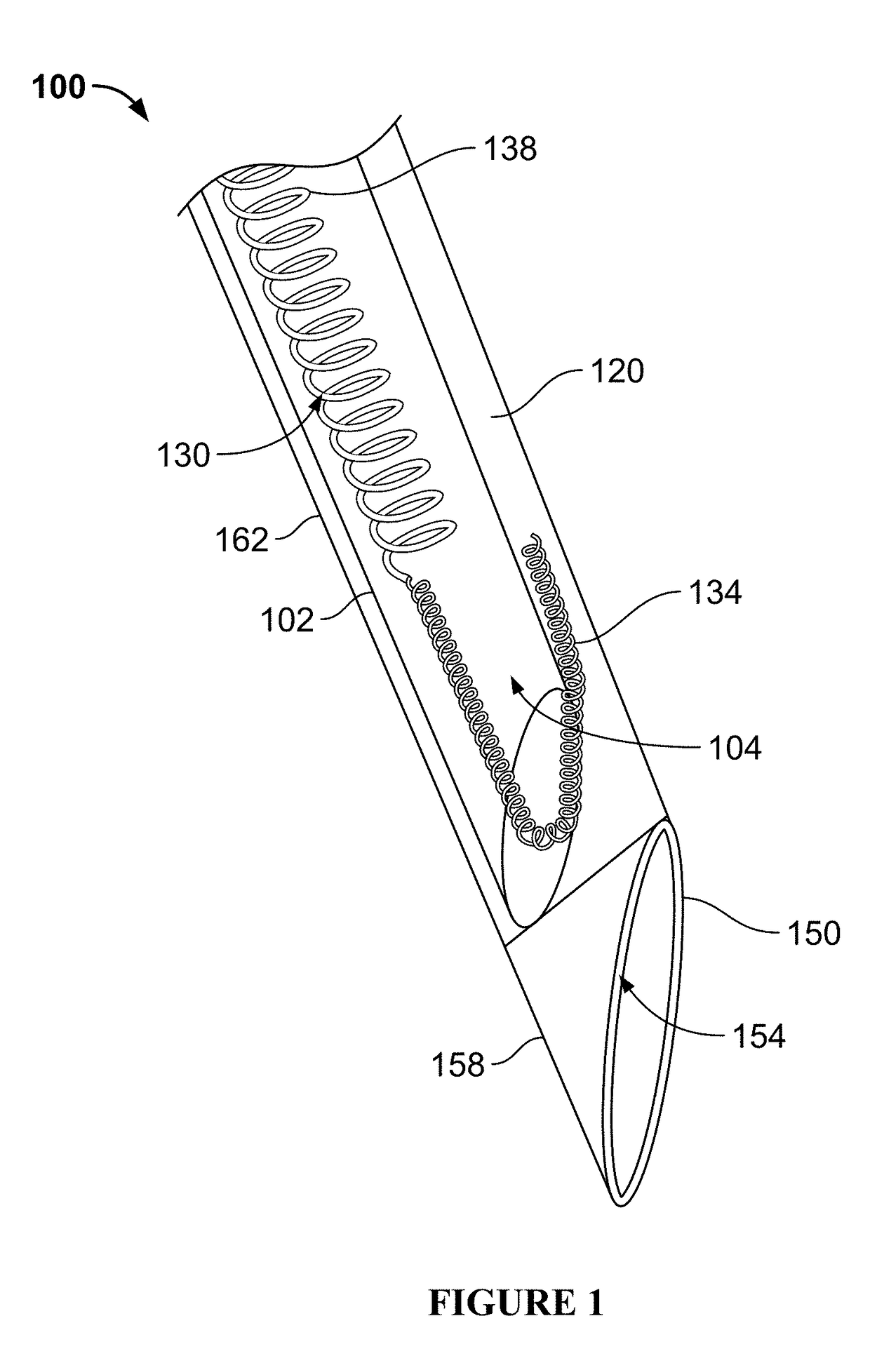
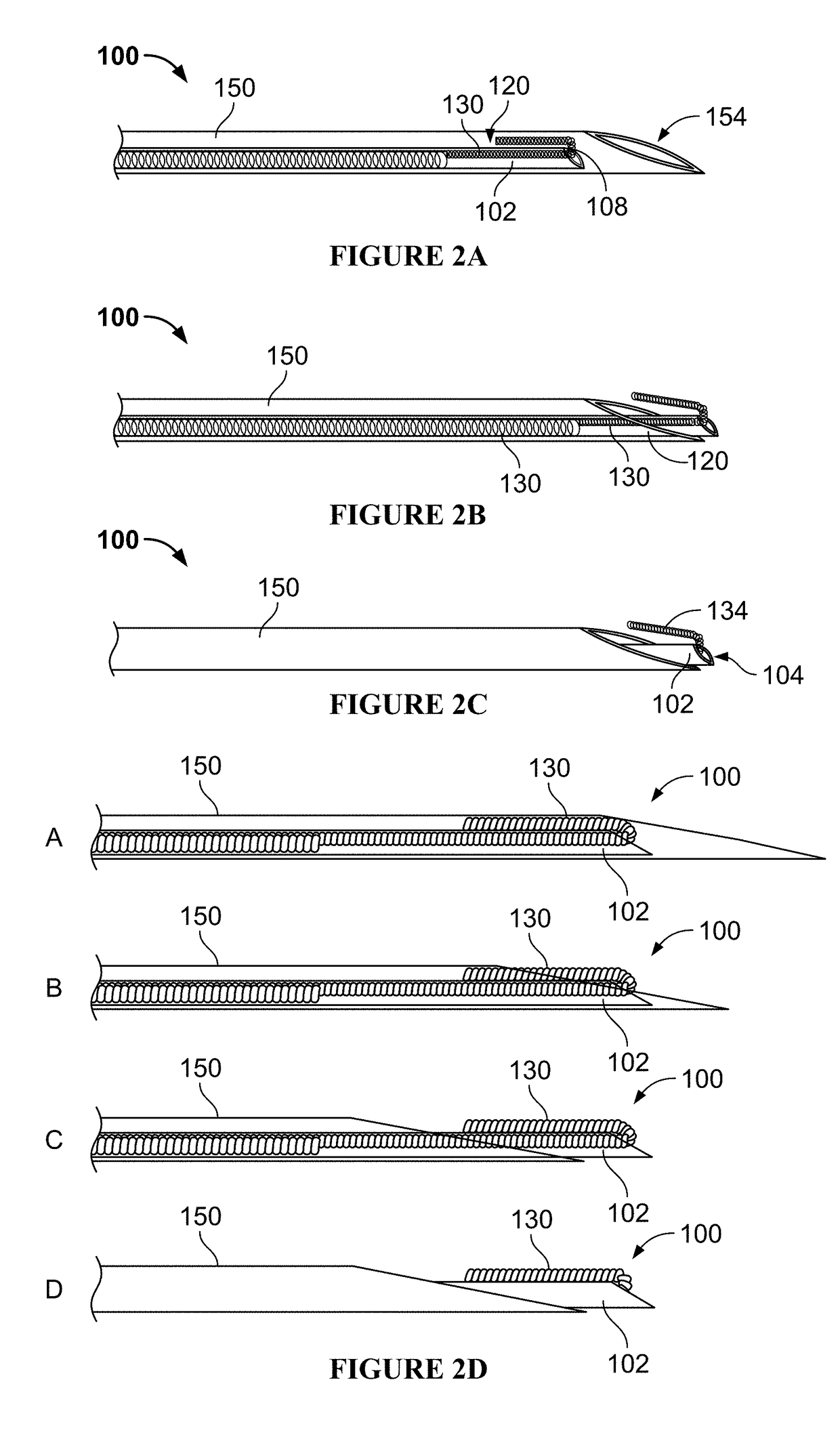
An introducing device for locating a tissue region and deploying an electrode is shown and described. The introducing device may include an outer sheath. An inner sheath may be disposed within the outer sheath. The inner sheath may be configured to engage an implantable electrode. In an example, the inner sheath may comprise a stimulation probe having an uninsulated portion at or near a distal end of the delivery sheath. The outer sheath may be coupled to a power source or stimulation signal generating circuitry at a proximal end. A clinician may control application of the stimulation signal to a tissue region via the outer sheath.

Description

CROSS REFERENCE TO RELATED APPLICATIONS[0001]This application is continuation in part of and claims priority to U.S. Utility application Ser. No. 15 / 388,128 filed on Dec. 22, 2016, which is a continuation of International Patent Application Serial Number PCT / US16 / 57267 filed on Oct. 17, 2016 which, in turn, claimed priority to U.S. Patent Application Ser. No. 62 / 242,205 filed on Oct. 15, 2015. The disclosure of these applications, along with any other United States patents and United States patent publications identified in this specification, are hereby incorporated by reference.FIELD OF INVENTION[0002]The present disclosure generally relates to locating a target tissue and deployment of a lead, and, more particularly, the disclosure relates to a system, apparatus, and methods for locating a target tissue region and deploying a lead via a single handheld device.BACKGROUND[0003]Electrical stimulation systems have been used for the relief of chronic and acute pain as well as many oth...

Claims


Application Information

Patent Timeline
IPC IPC(8): A61N1/372A61N1/04A61N1/05A61N1/36A61B17/34
CPCA61N1/37241A61B2017/3492A61N1/0502A61N1/36017A61N1/37205A61B17/3403A61B17/3468A61N1/0456A61N1/37264A61N1/36071A61N1/36125A61N1/36142A61N1/37247A61B2017/3413A61N1/0558A61B2017/3407
Inventor BOGGS, JOSEPH W.WONGSARNPIGOON, AMORNDEBOCK, MATTHEW G.MCGEE, MEREDITH J.SELL, DEVINSTROTHER, ROBERT B.
Owner SPR THERAPEUTICS
Learn More