Plastic bottle and base cup for a pressurized dispensing system

a technology of plastic bottles and pressurized dispensing, which is applied in the direction of liquid dispensing, packaging, supporting means, etc., can solve the problems of plastic aerosol bottles that could rupture, pressure inside plastic bottles can weaken the plastic structure, and the pressure inside plastic bottles can be difficult to control

Inactive Publication Date: 2017-11-30
SC JOHNSON & SON INC
View PDF18 Cites 45 Cited by
  • Summary
  • Abstract
  • Description
  • Claims
  • Application Information

AI Technical Summary

Benefits of technology

[0011]According to yet another aspect, our invention provides an aerosol dispensing system. The system includes a bottle having an opening at a top end and a rounded bottom at a bottom end, with the bottle being formed from a plastic material, and with the bottle containing an aerosol product under pressure. A spray mechanism is attached to the top end of the bottle, with the spray mechanism including a nozzle through which the aerosol product can be discharged. A base cup is adhered to the rounded bottom of the bottle with a hot melt adhesive, with the base cup including a pedestal adjacent to a center of the rounded bottom of the bottle, and the base cup having a flat bottom surface that allows the aerosol dispensing system to stand upright. The hot melt adhesive forms a layer between the pedestal and the rounded bottom of the bottle, with the hot melt adhesive being spread over the pedestal to prevent the rounded bottom of the bottle from contacting the pedestal.

Problems solved by technology

One of the biggest challenges in manufacturing plastic bottles for pressurized dispensing systems is providing the plastic bottle with enough structural integrity be able to withstand the internal pressure required for full evacuation of the product.
For example, an internal pressure required for compressed gas aerosols generally ranges from 45 PSIG to 200 PSIG at 70° F. whereas liquefied gas aerosols generally ranges from 17 PSIG to 108 PSIG at 70° F. If the plastic aerosol bottle is not provided with enough structural integrity to withstand such pressurization through the life of the dispensing system, then there is a risk that the plastic aerosol bottle could rupture.
In this regard, it is known that the pressure inside a plastic bottle can weaken the plastic structure over time, for example, by creating stress crazes and cracks in the plastic.
Moreover, a pressurized dispensing system might be subject to an event that tests the structural integrity of its plastic bottle, for example, when the bottle is dropped, or when the bottle is left in a high temperature environment that heats the contents of the bottle to thereby increase the already high internal pressure.
And the potential of a pressurized plastic bottle rupturing as a result of any of these events presents a clear safety risk to users of the dispensing system.
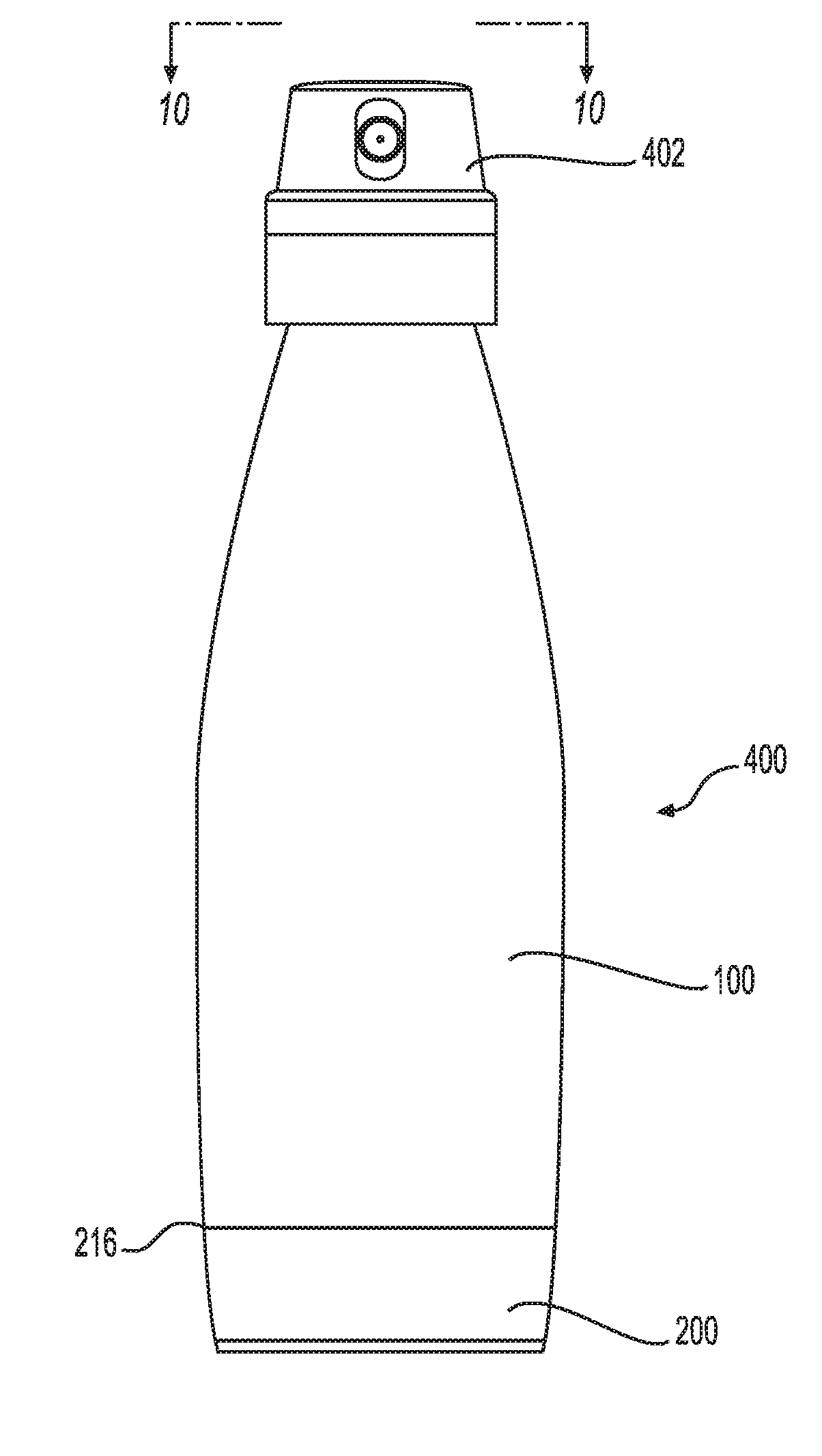
But, the use of a plastic bottle in a pressurized dispensing system presents a challenge with respect to making the system be able to stand upright.
While the base of the plastic bottle could be molded in a flat shape that allows the bottle to stand upright, it has been found that imparting such a flat shape often creates problems.
For example, contours that result from forming a vertically stable base in the bottle may be highly susceptible to stress crazing and cracking.
Further, a contoured base may be prone to bursting if the plastic bottle is dropped, and the base may deform if the pressure inside the plastic bottle increases, e.g., in elevated temperature environments.
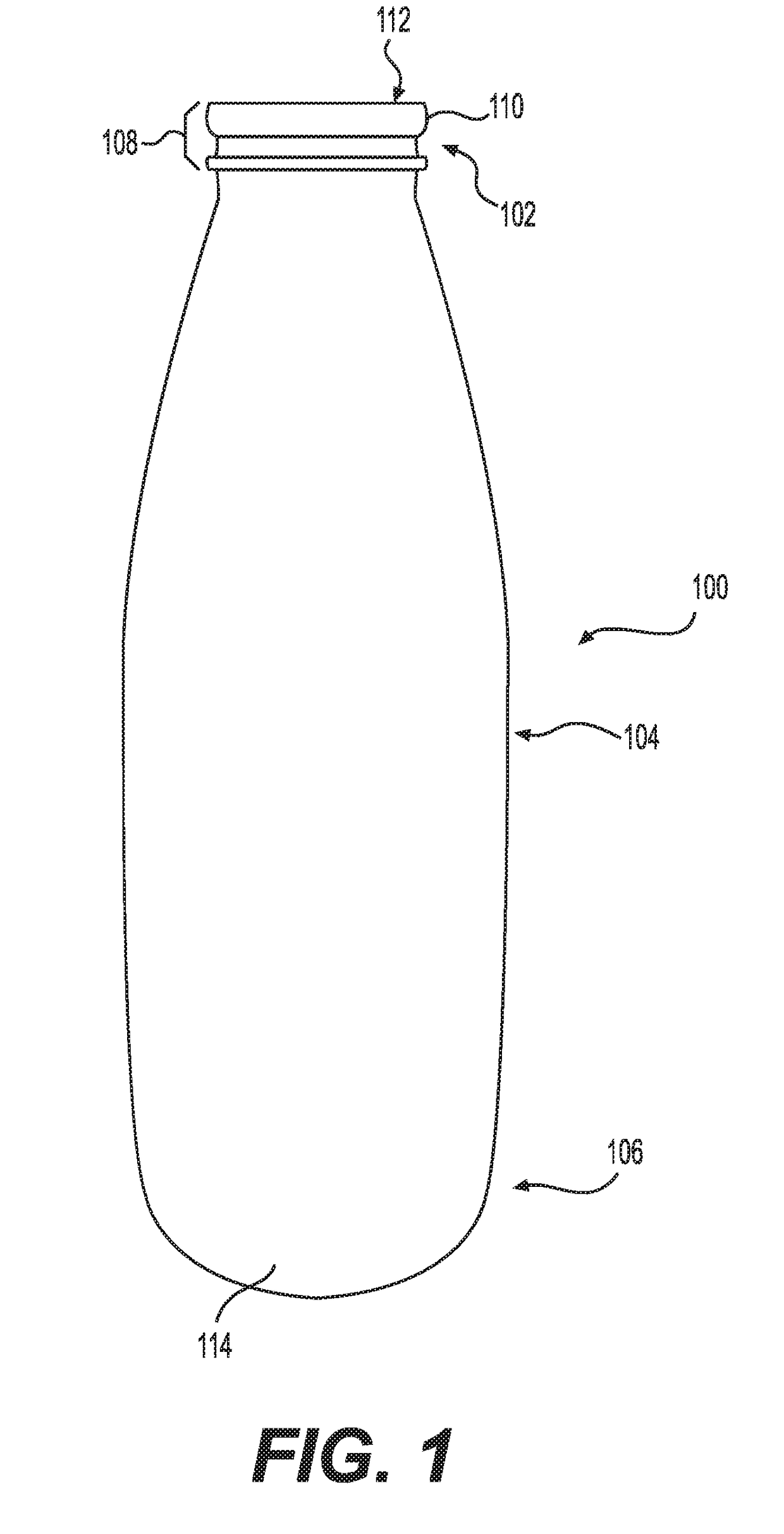
Further, as compared to a contoured base, a rounded plastic base in a plastic bottle is less prone to bursting when dropped and less easily deformed in elevated temperatures when the bottle is filled with a product and pressurized.
But, on the other hand, a rounded base does not provide a surface for making the plastic bottle stand upright.
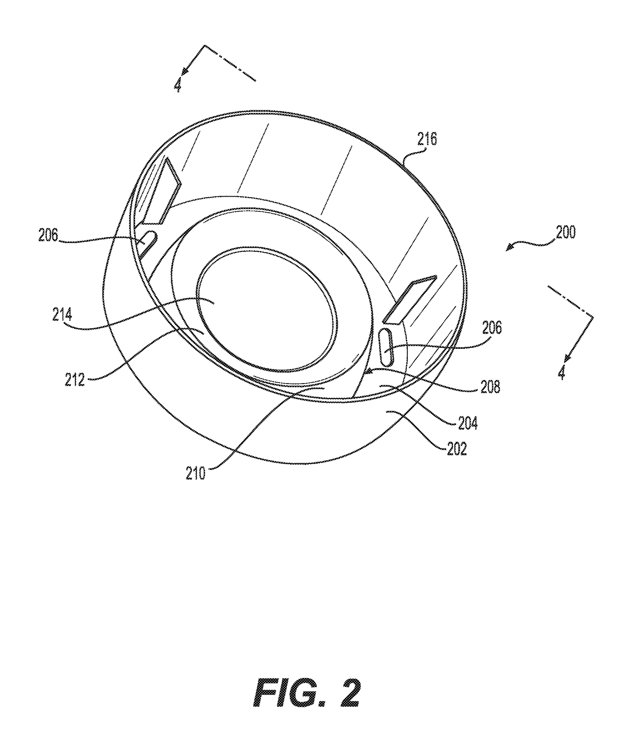
While a base cup is conceptually an easy solution for making a plastic bottle with a rounded bottom stand upright, in practice attaching a base cup to a plastic bottle as part of a pressurized dispensing system is a tremendous challenge.
The pressurized dispensing system will likely be exposed to handling and different environments before ever reaching the end consumer.
And, during handling or in different environments, the pressurized dispensing system may encounter conditions that may weaken the attachment between the base cup and bottle, such as varying temperatures and impacts.
If the attachment is weakened, the base cup might later become detached from the bottle when being used by the end consumer.
It is critical that this does not happen—separation of the base cup and bottle will at least result in unsatisfied consumers, if not result in significant safety hazards for the consumers.
While there are several techniques that could conceivably be used to securely attach a base cup to a plastic bottle, there are problems with most of these techniques, particularly in the context of pressurized dispensing systems.
For example, while welding techniques such as sonic, vibration, laser, and spin welding might be used to tightly attach a base cup to the bottle, the heat generated during the welding softens the material to a molten state, which in turn could lead to problematic stress risers when the bottle is subsequently filled with a product and pressurized.
Additionally, welding plastics requires similar plastic families to be used for both the base and base cup, which limits the resins that can be used.
However, such shaping of the bottom of the bottle may lead to the same types of problems that are found when the bottom of the bottle is made flat to make the bottle stand upright on its own.
And while there are many types of adhesives that might be considered, many of these adhesives are not suited for use in conjunction with a plastic bottle in a pressurized dispensing system.
For example, UV cured glues shrink when cured, which would put additional stress points on the plastic bottle, thereby leading to stress crazing or stress cracking.
As another example, solvent based structural adhesives, such as some epoxies, may not be suitable because these adhesives are generally difficult to cure and have poor impact resistance.

Method used


Image

  • Plastic bottle and base cup for a pressurized dispensing system
  • Plastic bottle and base cup for a pressurized dispensing system
  • Plastic bottle and base cup for a pressurized dispensing system

Examples


Embodiment Construction

[0022]Our invention generally relates to pressurized dispensing systems. More specifically, our invention relates to a dispensing system that includes a plastic bottle containing a product under pressure, with a base cup being attached to the plastic bottle to allow the system to stand upright.

[0023]In the descriptions that follow, we will sometimes explain features of our invention in the specific context of an aerosol dispensing system. Those skilled in the art will readily appreciate, however, that our invention is not limited to use with aerosol products. Rather, the pressurized dispensing systems described herein could alternatively be used in conjunction with products other than aerosols. For example, the dispensing systems described herein might be used to dispense foam products such as shaving cream or soap, or used to dispense food products such as soda, whipped cream, or processed cheese.

[0024]FIG. 1 is a side view of a plastic bottle 100 for use in a pressurized dispensin...


PUM


Abstract

A container for a pressurized dispensing system. The container includes a plastic bottle and a base cup bonded to a rounded bottom of the plastic bottle with a hot melt adhesive. The base cup has a bottom surface that allows the container to stand upright. A method of forming the container is also provided wherein hot melt adhesive is deposited in a recessed region in a top wall of a pedestal of the base cup, and a center region of the rounded bottom of the plastic bottle is pressed against the hot melt adhesive such that the adhesive spreads out over the recessed region and the rest of the top wall of the pedestal. After the hot melt adhesive cools, the bottle is securely bonded to the base cup.

Description

BACKGROUNDField of the Invention[0001]Our invention generally relates to a pressurized dispensing system, such as a system that dispenses an aerosol product. More specifically, our invention relates to a dispensing system that includes a plastic bottle containing a product under pressure, with a base cup being attached to the plastic bottle to allow the system to stand upright.Related Art[0002]Pressurized dispensing systems, such as systems used to dispense aerosol products, have conventionally included metallic (e.g. steel or aluminum) containers for containing the product under pressure before it is dispensed from the system. Examples of products that are dispensed with such systems include air fresheners, fabric fresheners, insect repellants, paints, body sprays, hair sprays, shoe or footwear spray products, whipped cream, and processed cheese. Recently, there has been increased interest in using plastic bottles as an alternative to metallic containers in pressurized dispensing s...

Claims


Application Information

Patent Timeline
Patent Type & Authority Applications(United States)
IPC IPC(8): B65D83/38B65D1/02B65D83/28
CPCB65D83/38B65D1/023B65D2207/00B65D83/28B65D1/0261B65D23/001
Inventor WOLAK, CHRISTOPHER P.CARLSON, DAVID R.MCGRATH, DANIEL S.STENMARK, NILES
Owner SC JOHNSON & SON INC
Why Eureka
Try Eureka