System and method for visible light communications with multi-element transmitters and receivers
- Summary
- Abstract
- Description
- Claims
- Application Information
AI Technical Summary
Benefits of technology
Problems solved by technology
Method used
Image

Examples
example 1
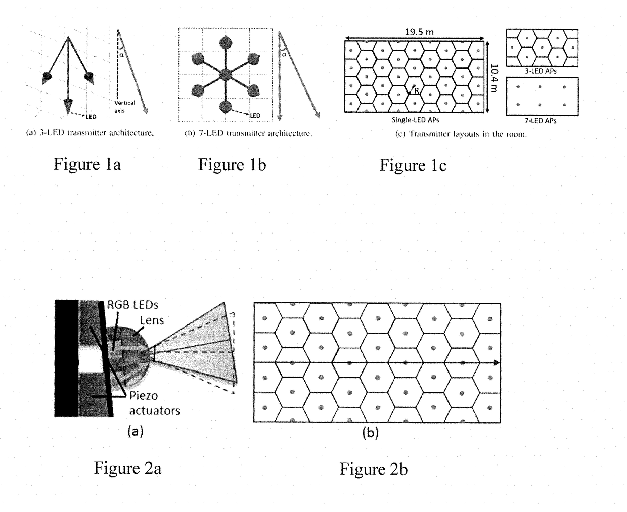
[0211]Simulations were conducted to prove the concepts and techniques of the present invention. In this example, the performance of initial assignment and greedy algorithms was evaluated. The simulations assumed that the LEDs had a Lambertian pattern. A large room with the dimensions of 19 m×10 m×4 m was the basis for the simulation. The layout of LEDs and APs for this example is shown in FIG. 17. Six APs were considered, each having 7 LEDs. In total, there were 42 LEDs to be shared by the users. Each AP was structured such that one LED was directed towards the floor, and the rest were tilted with a 45° divergence angle. All APs were located at ceiling height, and the receiver was assumed to be at 0.85 m in height and directed upwards. Multiple realizations were performed by dropping the receiver at random locations.
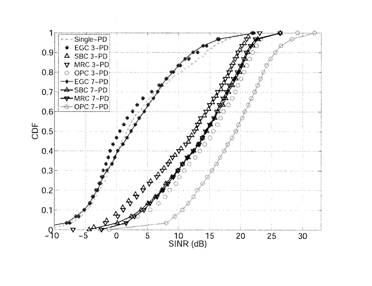
[0212]In FIG. 18 and FIG. 19, the CDFs of SINRs for HR-based and WSP-based methods are shown, respectively. The CDFs were evaluated based on 60 different realizations, a...
example 2
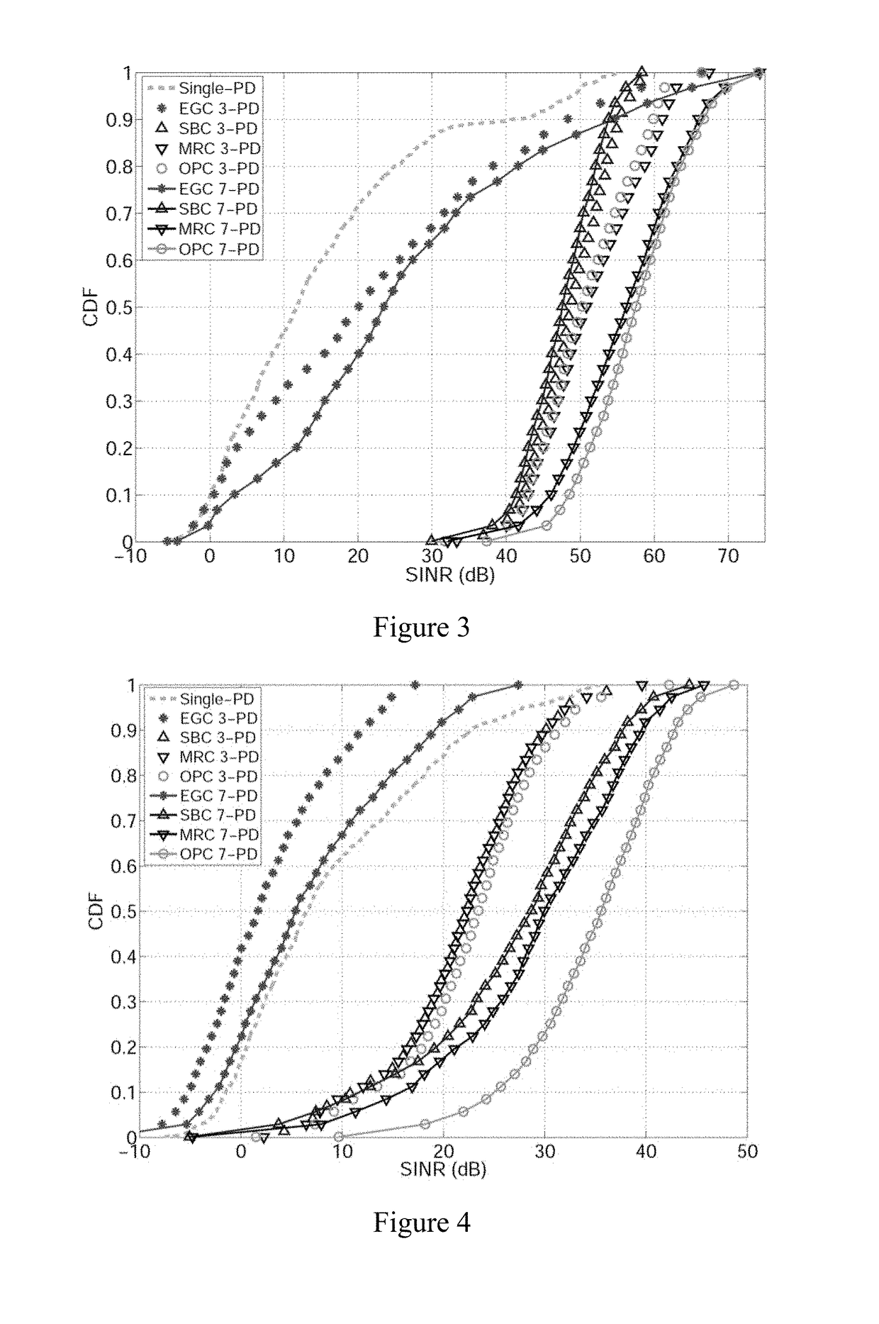
[0216]A second set of simulations using the techniques of the present invention was conducted, including the consideration of multipath reflections. In a first simulation, a large room with dimensions of 19.5 m×10 m×4 m was considered. The layout of LEDs and APs in the room was as shown by the “large room” in FIG. 24(a). Six APs were considered, each having 7 LEDs. In total, there were 42 LEDs to be shared by the users. The second setup was smaller and was designed to compare the performance of the algorithms to the optimal solution. Since the optimal solution is prohibitively complex to find for a large number of LEDs, a smaller room with fewer LEDs was used. The “small room” had dimensions of 6.5 m×10 m×4 m with 6 APs, each having 7 LEDs, as shown in FIG. 24(a). Each AP was structured such that one LED was directed towards the floor, and the rest were tilted with a 45° divergence angle as in FIG. 24(b). All APs were located at ceiling height, and the receiver was assumed to be at ...
PUM
 Abstract
Description
Claims
Application Information
 - Generate Ideas
- Intellectual Property
- Life Sciences
- Materials
- Tech Scout
- Unparalleled Data Quality
- Higher Quality Content
- 60% Fewer Hallucinations
Browse by: Latest US Patents, China's latest patents, Technical Efficacy Thesaurus, Application Domain, Technology Topic, Popular Technical Reports.
© 2025 PatSnap. All rights reserved.Legal|Privacy policy|Modern Slavery Act Transparency Statement|Sitemap|About US| Contact US: help@patsnap.com