

Centrifugal separator for cleaning gas
- Summary
- Abstract
- Description
- Claims
- Application Information
AI Technical Summary
Benefits of technology
Problems solved by technology
Method used
Image

Examples
Embodiment Construction
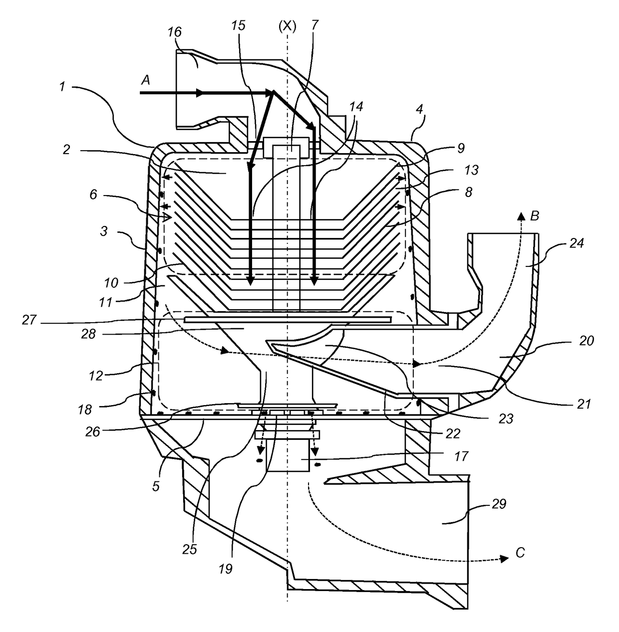
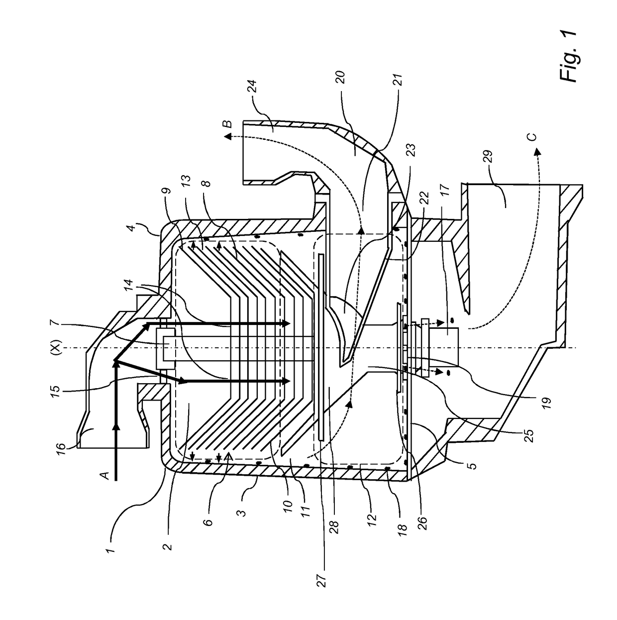
[0079]The centrifugal separator according to the present disclosure will be further illustrated by the following description of an embodiment with reference to the accompanying drawings.
[0080]FIG. 1 shows a schematic section view of a centrifugal separator according to an embodiment of the present disclosure. The centrifugal separator comprises a stationary casing 1, which is configured to be mounted to a combustion engine (not disclosed), especially a diesel engine, at a suitable position, such as on top of the combustion engine or at the side of the combustion engine. The stationary casing 1 encloses a separation space 2 through which a gas flow is permitted. The stationary casing 1 comprises, or is formed by, a surrounding side wall 3, a first end wall 4 (in the embodiments disclosed an upper end wall) and a second end wall 5 (in the embodiments disclosed a lower end wall). The surrounding side wall 3 has a circular cross-section with a radius R from the axis (X) of rotation to t...
PUM
| Property | Measurement | Unit |
|---|---|---|
| Angle | aaaaa | aaaaa |
| Radius | aaaaa | aaaaa |
Abstract
Description
Claims
Application Information