Thermal response switch

a technology of thermally responsive plates and switches, which is applied in the direction of machines/engines, liquid fuel engines, positive displacement liquid engines, etc., can solve the problems of not being able to achieve sufficient self-heating of components such as heaters and thermally responsive plates, resistivity can only be increased to a limited level, and limit to increasing heating values

Inactive Publication Date: 2017-12-07
UBUKATA IND CO LTD
View PDF8 Cites 0 Cited by
  • Summary
  • Abstract
  • Description
  • Claims
  • Application Information

AI Technical Summary

Benefits of technology

[0015]According to the thermally responsive switch of the present invention, the narrow portion serving as a fusing portion is provided on the end portion located in one side of the middle vertical portion where no other heating element exists among the two widthwise end portions of the middle vertical portion. According to such co...

Problems solved by technology

Thus, it is not possible for components such as the heater and the thermally responsive plate to be sufficiently self-heated under the structure of the conventional thermally responsive switch 101.
However, since limited types of metals are used as bimetal and tri-metal of the thermally responsive plate for example, resistivity can only be increased to a limited level.
Hence, there is a limit to increasing the heating value by modifying the materials of the thermally responsive plate.
However, since drive force for opening and closing the movable contact needs to be secured for the thermally responsive plate, there is also a limit to thinning the thermally responsiv...

Method used


Image

  • Thermal response switch
  • Thermal response switch
  • Thermal response switch

Examples


Embodiment Construction

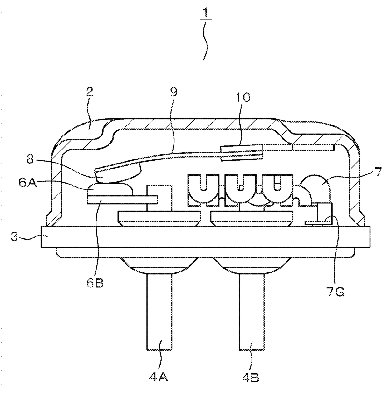
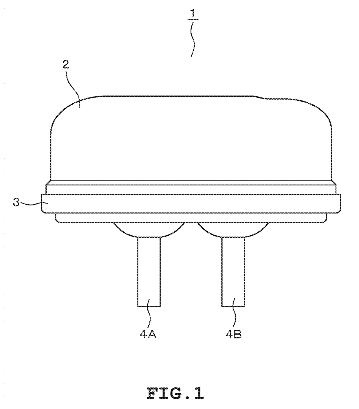
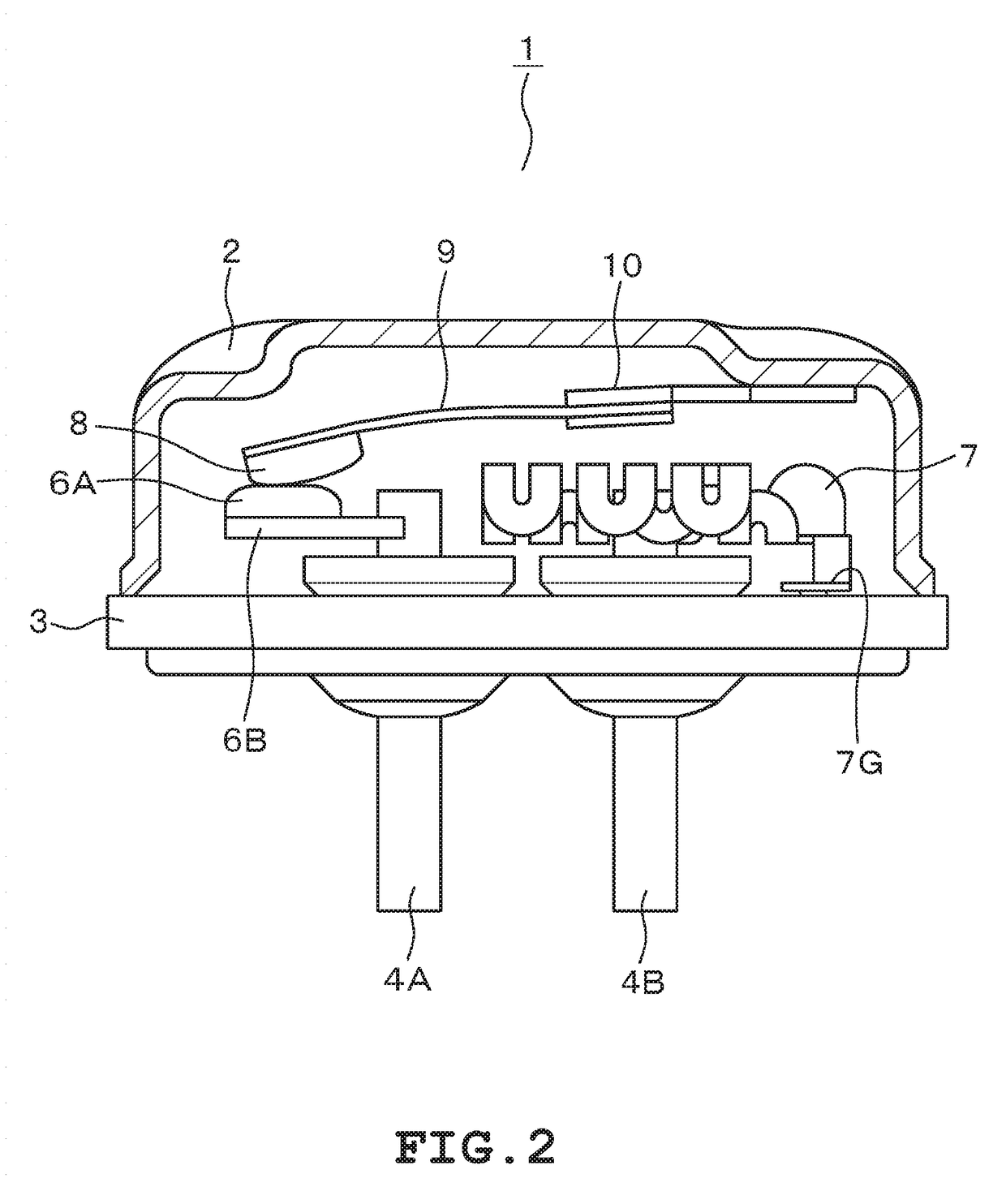
[0030]A description will be given hereinafter on one embodiment of a thermally responsive switch to which the present invention is applied with reference to the drawings. As shown in FIGS. 1 and 2, a thermally responsive switch 1 is an airtight container configured of a metal housing 2 and a lid plate 3. The housing 2 is formed into a long-dome shape having an open end. The lid plate 3 is airtightly fixed to the open end of the housing 2 by welding or the like. Conductive terminal pins 4A, 4B made of metal are inserted into two through holes provided in the lid plate 3. These conductive terminal pins 4A, 4B are fixed by an electrically insulating filler such as glass. Thus, the conductive terminal pins 4A, 4B are airtightly fixed in an electrically insulated state.

[0031]A fixed contact 6A is fixed, through a conductive fixed contact support 6B, to a portion of the conductive terminal pin 4A located inside the airtight container. Also, a thermally responsive plate 9 configured of bim...


PUM


Abstract

A thermally responsive switch includes a heating element with a meandering portion formed of a metal plate. The meandering portion is bent twice with respect to reference axes extending in a longitudinal direction of a housing. The meandering portion includes an outer vertical portion that is perpendicular to an inner surface of a lid plate, an inner vertical portion that is perpendicular to the inner surface of the lid plate, and a middle vertical portion that is disposed between the outer vertical portion and the inner vertical portion and is perpendicular to the inner surface of the lid plate. The middle vertical portion has a narrow portion narrower than a width of the middle vertical portion. The narrow portion is provided on an end portion located in one side of the middle vertical portion where no other heating element exists among the two widthwise end portions of the middle vertical portion.

Description

CROSS-REFERENCE TO RELATED APPLICATIONS[0001]This is a National Stage Entry into the United States Patent and Trademark Office from International PCT Patent Application No. PCT / JP2014 / 084082, having an international filing date of Dec. 24, 2014, the entire content of which is incorporated herein by reference.FIELD OF THE INVENTION[0002]The present invention relates to a thermally responsive switch used as a protection device for motors or the like.BACKGROUND OF THE INVENTION[0003]Many suggestions have been made for this type of thermally responsive switch which utilizes a thermally responsive element such as a bimetal. An example of such thermally responsive switch will be described with reference to FIGS. 10 and 11. A thermally responsive switch 101 is provided with a metal housing 102 and a lid plate 103. The lid plate 103 is fixed to an opening of the housing 102 by welding to form an airtight container. Through holes are formed through the lid plate 103. Metal conductive termina...

Claims


Application Information

Patent Timeline
IPC IPC(8): H01H37/54F04B39/00F04C29/00H01H37/14
CPCH01H37/5427H01H37/14F04B39/00F04C29/00H01H37/5418H01H2037/5463
Inventor YAMAGUCHI, YOSHIO
Owner UBUKATA IND CO LTD
Why Eureka
Try Eureka