Underwater engagement of tubular members

Active Publication Date: 2017-12-14
SAIPEM SPA
View PDF5 Cites 0 Cited by
  • Summary
  • Abstract
  • Description
  • Claims
  • Application Information

AI Technical Summary

Benefits of technology

[0015]The position of the stop relative to the pad is preferably adjustable. That provides a simple way of adjusting the degree of compression in the compressed spring arrangement and therefore the force with which the compressed spring arrangement presses, in use, against the tubular member. A screw threaded member may be provided for defining the position of the stop. Screwing of the screw threaded member may move it in a radial direction. Whilst it is possible for the stop to be formed integrally with the screw threaded member, it is preferred that the stop is separate from the screw threaded member, with the stop being pressed, in use, against the screw threaded member which thereby defines the position of the stop. A further screw threaded locking member may be provided for screwing along the same thread as the screw threaded member to lock the screw threaded member in the position that defines the position of the stop.
[0016]The screw thread of the screw threaded member defining the position of the stop and/or of the screw threaded locking member may be trapezoidal. The screw threaded surface of the thread may be treated to lower the coefficient of friction between contacting surfaces. The screw threaded surface of the thread may be treated with a high velocity oxyg

Problems solved by technology

A difficulty with such an approach is that the reliability of a hydraulic system is most likely to become an issue over time and some main

Method used


Image

  • Underwater engagement of tubular members
  • Underwater engagement of tubular members
  • Underwater engagement of tubular members

Examples


Example

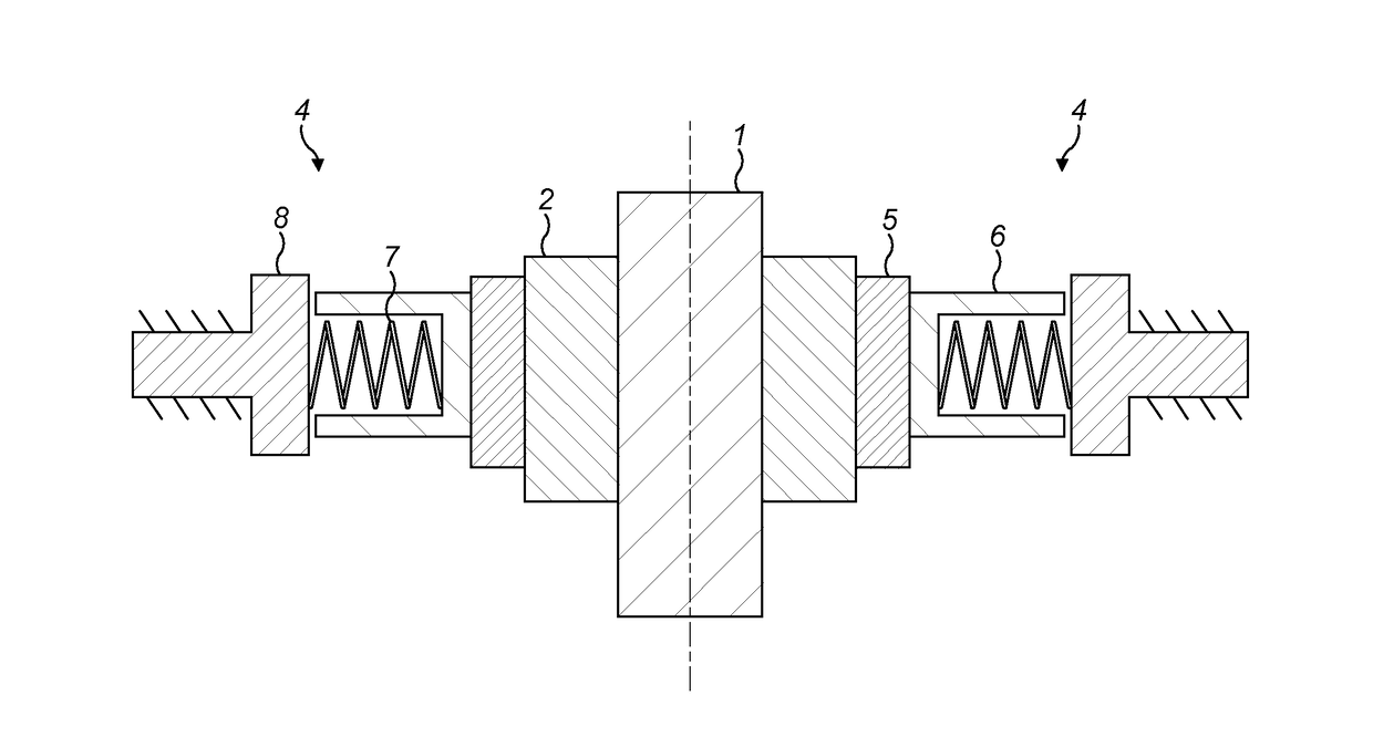
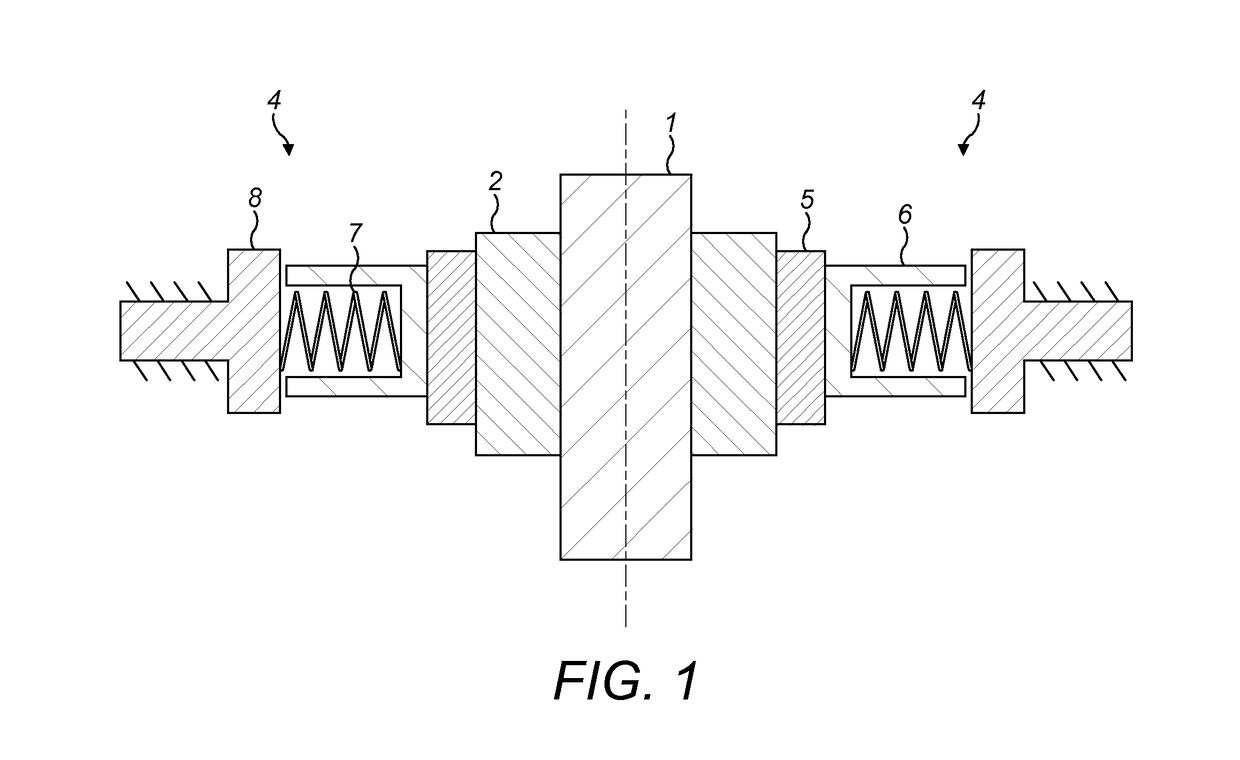
[0032]FIG. 1 shows diagrammatically an underwater connection system embodying the invention. A tubular member 1 having a collar 2 fixed thereto is to be held in place by a connection assembly which in diagrammatic FIG. 1 is shown as comprising a pair of sub-assemblies 4 on opposite sides of the tubular member 1. Each sub-assembly comprises a pad 5, a compressed spring assembly comprising a spring casing 6 and a spring 7 and an external structure 8 which is fixed in space, for example to the sea-floor.

[0033]The springs 7 of each compressed spring assembly are pre-loaded so that there is a substantial spring pressure, in one particular example 750 kN, pressing each pad 5 against the collar 2 of the tubular member 1. In that way the tubular member is resiliently located in a horizontal plane.

[0034]The faces of the pads 5 in contact with the collar 2 are provided with low friction surfaces to allow vertical (axial)sliding movement of the collar 2 relative to the pads 5. In a particular ...


PUM


Abstract

A connection assembly for engaging a tubular member underwater to restrain the tubular member from radial movement relative to the connection assembly includes a plurality of pads for engaging the tubular member at circumferentially spaced positions; and a plurality of biasing arrangements, each for biasing a respective pad radially inwardly into engagement with the tubular member; wherein each biasing arrangement includes a pre-loadable, mechanical, compressed spring arrangement for resiliently pressing its respective pad against the tubular member. The assembly need not employ any hydraulic components.

Description

FIELD OF THE INVENTION[0001]The present invention relates to a connection assembly for engaging a tubular member underwater to restrain the tubular member from radial movement. The invention also relates to a method of engaging a tubular member underwater.BACKGROUND OF THE INVENTION[0002]In the offshore oil and gas industry and in similar technologies it is common to provide tubular members of various kinds extending down into the sea bed. An underwater structure is often provided, for example, on the seabed for restraining and / or guiding movement of the tubular member. Such arrangements may apply in a wide variety of circumstances and in some of those circumstances the structure is desired to restrain the tubular member passing through it from radial movement relative to the structure. Typically in the offshore industry, the forces which the restraint is required to resist are very high and conventionally such forces are provided by hydraulic systems. It is possible to devise a ver...

Claims


Application Information

Patent Timeline
IPC IPC(8): E21B17/10F16L3/205E21B33/038F16L1/12
CPCE21B17/1078F16L3/205F16L1/123E21B33/038E21B41/0007E21B19/24
Inventor SERENA, ALBERTOLAZZARIN, DIEGOCADEDDU, GABRIELE
Owner SAIPEM SPA
Why Eureka
Try Eureka