Combination air valve

Active Publication Date: 2017-12-14
DEZURIK
View PDF5 Cites 2 Cited by
  • Summary
  • Abstract
  • Description
  • Claims
  • Application Information

AI Technical Summary

Benefits of technology

[0014]The float shaft is in some cases solid, while in other cases hollow. Also, the float shaft can terminate such that it is open to the exterior, or can terminate in an enclosed sealing cap. When the float shaft terminates in a sealed cap the shaft typically has a vent path leading from the main body of the valve to allow equal pressure on both sides of the float shaft, which reduces extrusion forces caused by internal pressures. The reduction or elimination of these extrusion forces allows for a valve that can be operated without linkages or other mechanical advantage at higher pressure. In certain embodiments the venting valve has a float shaft with a variable diameter, and the variations in diameter can be used to close and open seals around the float shaft, in particular aro

Problems solved by technology

However, such designs suffer from a number of shortcomings, including the problem that each air release valve must be customized for different uses because of the varying pressures, flow rates, etc. that are observed along a pipeline.
Further, existing air release valves often have limited pressure ranges, and cannot operate at the wide range of pressures that are sometimes experienced in pipelines.
Specifically, higher pressure air re

Method used


Image

  • Combination air valve
  • Combination air valve
  • Combination air valve

Examples


Embodiment Construction

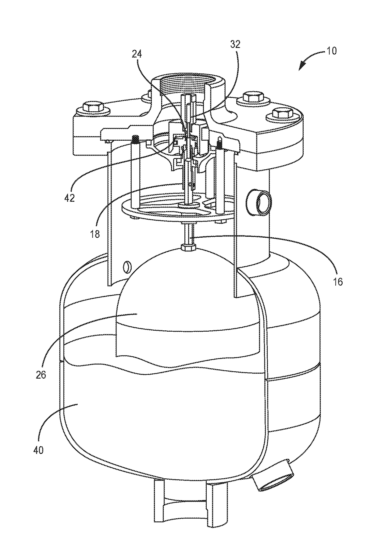
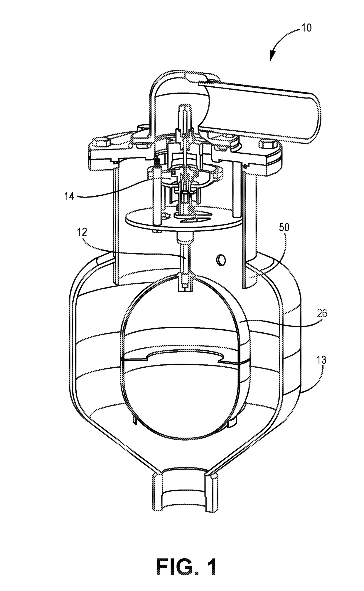
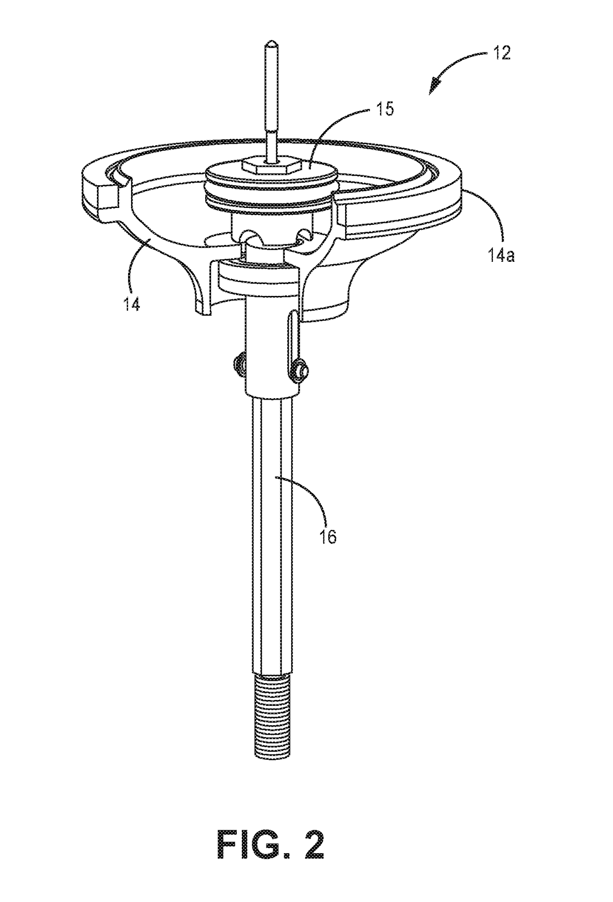
[0036]The present invention is directed to an air release valve. In certain embodiments the air release valve includes a piston assembly having a main disc, a piston head located above the main disc, a float below the main disc, and a float shaft joining the float to the piston. The float shaft contains, in some configurations, a hollow interior allowing gases to flow from an upper to lower portion of the float shaft to equalize pressure around sealing elements on the float shaft. This pressure equalization is such that extrusion forces on the float shaft can be significantly reduced, if not eliminated, thereby allowing improved performance at high pressures as well as at greater pressure differentials between the interior and exterior of the valve.

[0037]When no media is in the valve, the float is at the bottom of the valve body and the main disc is in a down position. Having the main disc in the down position allows for gases to readily leave the valve through a top opening. As med...


PUM


Abstract

The present disclosure is directed to a combination air valve that uses buoyancy to lift seals into place, preventing media from escaping from the valve. Once the seals are in place, pipeline pressure is used to open and close the valve. The combination air valve includes a low flow vent configured with a pressure equalizing configuration allowing for reduced extrusion forces along the low flow vent, allowing vertical movement of a float shaft at high valve gas pressures with reduced forces.

Description

[0001]This application claims the benefit of U.S. Provisional Application No. 62 / 348,434, filed Jun. 10, 2016, the contents of which are herein incorporated by reference.FIELD OF THE INVENTION[0002]The present application is directed to valves, in particular to air release valves for use in pipelines and similar media handling systems.BACKGROUND OF THE INVENTION[0003]Pipelines, and similar media handling and conveying systems, often accumulate air within them. The air can accumulate, for example, from bubbles within the media being conveyed (as used herein, media refers to a liquid that may contain solid or semi-solid material), by gasses that vent from the media, or during filling and emptying cycles of the pipeline.[0004]It is often desirable to remove the accumulated air from the pipelines, and air release valves have been developed for this purpose. Traditional air release valves use the buoyancy of a float to close the valve. However, such designs suffer from a number of shortc...

Claims


Application Information

Patent Timeline
IPC IPC(8): F16K31/22F16K31/122F16K24/04
CPCF16K31/22F16K31/122F16K24/044E03F5/08F16L55/07
Inventor KALTHOFF, ADAM L.HALVORSON, FORREST
Owner DEZURIK
Why Eureka
Try Eureka