Tunnel diversion system suitable for water-rich stratum and construction method

A water-rich stratum and tunnel construction technology, applied in tunnels, tunnel linings, drainage, etc., can solve the problem of water-rich sections of surrounding rocks that are not enough to deal with concentrated strands of water, affecting the smoothness of the tunnel drainage system and the drainage capacity of the waterproof and drainage system Limitation and other problems, to achieve the effect of eliminating the risk of extrusion deformation, low construction cost, and low space occupancy rate

Pending Publication Date: 2022-03-08
GUIZHOU TRANSPORTATION PLANNING SURVEY & DESIGN ACADEME
View PDF0 Cites 0 Cited by
  • Summary
  • Abstract
  • Description
  • Claims
  • Application Information

AI Technical Summary

Problems solved by technology

However, limited by the diameter of the drainage pipe, the drainage capacity of the conventional tunnel waterproof and drainage system is limited, which is not enough to deal with the situation of large strands of water
At the same time, the radial stiffness of the circumferential drainage pipes installed between the primary support and the secondary lining is extremely limited, and there is a possibility of extrusion deformation or even rupture during the construction of the secondary lining, which seriously affects the smoothness of the tunnel drainage system
[0003] It can be seen that the existing tunnel waterproof and drainage system that uses drainage pipes to divert and drain groundwater has certain limitations in function, and it is not enough to deal with the water-rich section of the surrounding rock with concentrated strands of water. Once the groundwater cannot be diverted and drained in time, There are certain construction risks and operational risks

Method used


Image

  • Tunnel diversion system suitable for water-rich stratum and construction method
  • Tunnel diversion system suitable for water-rich stratum and construction method
  • Tunnel diversion system suitable for water-rich stratum and construction method

Examples


Embodiment Construction

[0040] A preferred embodiment of the present invention will be described in detail with reference to the accompanying drawings. It should be understood that preferred embodiments are intended to illustrate the invention, not to limit the scope of the invention.

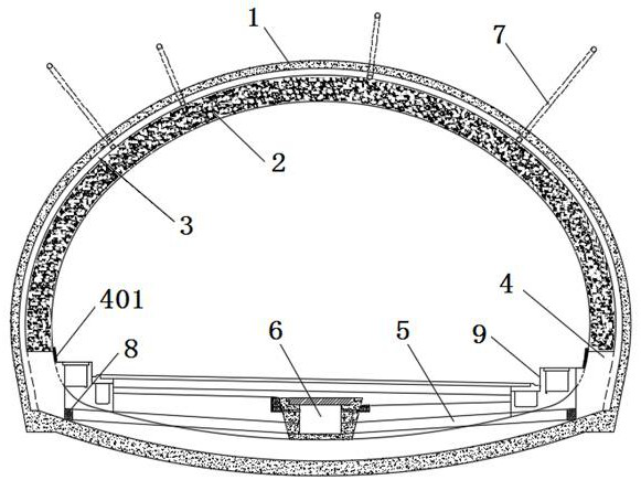
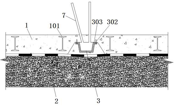
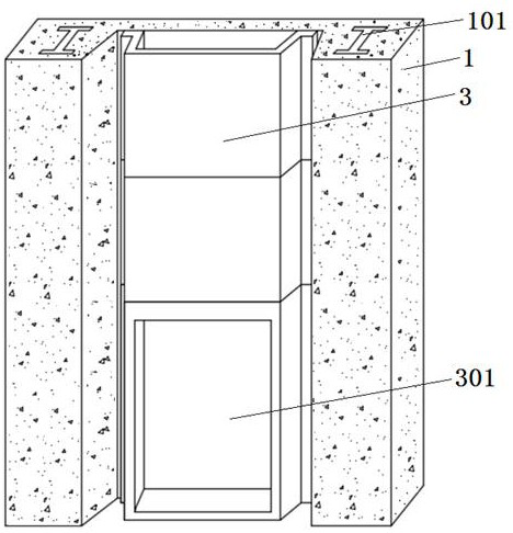
[0041] Such as Figure 1 - Figure 5 As shown, a tunneling system suitable for the rich floors, including a ring groove structure 3 that is provided between the initial support 1 two 榀 字 字 101 and corresponding to the tunnel profile; the annular groove steel structure 3 two The end is provided with a water port 301, and the water port 301 is in turn through the side wall collector 4, and the lateral dark groove 5 is in communication with the central drain 6.

[0042]Surrounding the tunnel equipped with a number of radial or diagonal structure of the drain hole 3 an annular channel 7 of communication. The radial or oblique drain provides a drain passage in the vicinity paragraph. According to the flexible setting of the wate...


PUM


Abstract

The invention discloses a tunnel diversion system suitable for a water-rich stratum and a construction method. The tunnel diversion system comprises an annular channel steel structure which is arranged between two truss I-shaped steel of a primary support and corresponds to the outline of a tunnel. Water outlets in the two ends of the annular channel steel structure communicate with the center drainage ditch through the side wall water collecting wells and the transverse buried grooves in sequence. In the tunnel excavation process, it is found that strand-shaped water flows out of the surrounding rock surface or the primary support surface, a water outlet and drainage groove can be formed between two truss I-shaped steel in front of and behind a concentrated water outlet point, and an annular channel steel structure is arranged in the drainage groove for water drainage. According to the method, construction is simple, pre-judgment expanding excavation is not needed, universality is high, the annular channel steel structure is buried in the gap between the two truss I-shaped steel for drainage, the annular drainage capacity of the tunnel and the reliability of the drainage structure are greatly improved, the drainage requirement of the water-rich stratum tunnel can be effectively met, and practicability is high.

Description

Technical field [0001] The present invention relates to a tunnel throughput system and construction method suitable for the rich floors, which are in the field of tunnel construction, especially for tunnel drainage structures in surrounding rockfishing paragraphs. Background technique [0002] The tunnel construction is often encountered in the rock rich section. If the treatment of groundwater during construction is not in place, it may have adverse effects on the tunnel support structure, which will leave a hidden danger for tunnel operation safety. For the case of the tunnel crossing the rich segment of the rock, relatively reliable practice is to direct the groundwater around the tunnel to reduce the water pressure acting on the tunnel structure, and reduce the risk of tunnel leakage in the later operational stage. However, it is limited to the pipe diameter of the drain pipe, the routine tunnel anti-drainage system is limited, and it is not sufficient to cope with the large ...

Claims


Application Information

Patent Timeline
Patent Type & Authority Applications(China)
IPC IPC(8): E21F16/02E21D11/10E21D11/14E21D11/38
CPCE21F16/02E21D11/105E21D11/14E21D11/38
Inventor 胡强杨洪李本云张安睿春军伟杨春平邓少军周立
Owner GUIZHOU TRANSPORTATION PLANNING SURVEY & DESIGN ACADEME
Why Eureka
Try Eureka