

Water Meter With Magnetically Driven Flow Restriction Valve
- Summary
- Abstract
- Description
- Claims
- Application Information
AI Technical Summary
Benefits of technology
Problems solved by technology
Method used
Image

Examples
Embodiment Construction
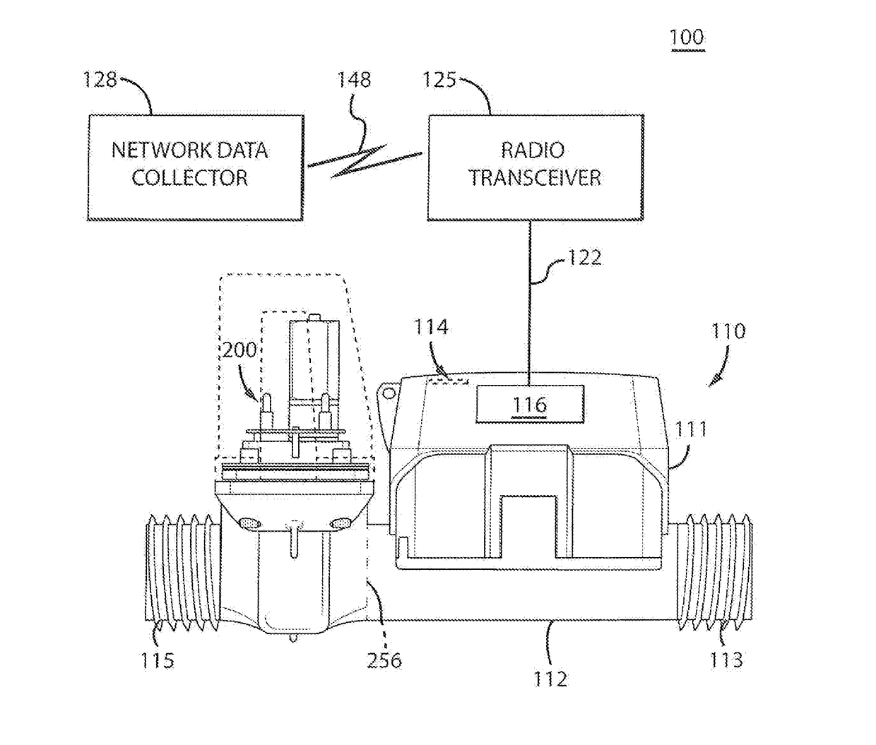
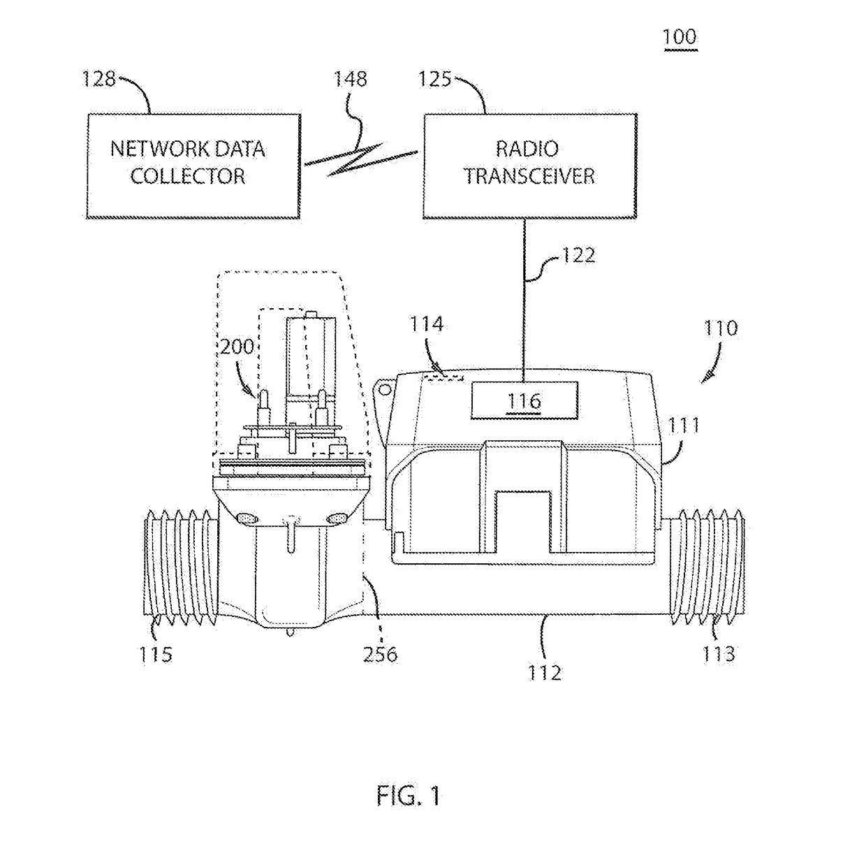
[0023]FIG. 1 shows a utility metering system 100, according to an exemplary embodiment. An ultrasonic water meter 110 includes a meter housing 111, an integral magnetically driven gate valve 200, and a pressure vessel 112 having an upstream spud end 113 and a downstream spud end 115. The spud ends 113, 115 of the pressure vessel 112, although shown as threaded pipe ends, can be replaced by coupling flanges in larger sized meters. Meter housing 111 may be configured to be totally encapsulated, weatherproof and UV-resistant. The meter housing 111 includes a display 114 that may be configured as a 9-digit LCD display for displaying a measured rate of flow, a reverse-flow indication, alarms, etc. to complete the enclosure as is known in the art.
[0024]Ultrasonic water meter 110 may be configured with a solid state, ultrasonic measurement system 116. As water flows into the measuring tube, pressure vessel 112, through the upstream spud end 113, ultrasonic signals are sent consecutively in...
PUM
 Abstract
Description
Claims
Application Information