Electronic beam machining system

a technology of electronic beam machining and photolithography, which is applied in the direction of electric discharge tubes, graphene, and nano-carbon, etc., can solve the problems of high cost, complicated and lower efficiency of conventional electronic beam machining system

Active Publication Date: 2017-12-14
TSINGHUA UNIV +1
View PDF3 Cites 3 Cited by
  • Summary
  • Abstract
  • Description
  • Claims
  • Application Information

AI Technical Summary

Problems solved by technology

However, the conventional electronic beam machining system usually has only one electron gun and can only emit a single electron beam.
Thus, the conventional electron

Method used


Image

  • Electronic beam machining system
  • Electronic beam machining system
  • Electronic beam machining system

Examples


Embodiment Construction

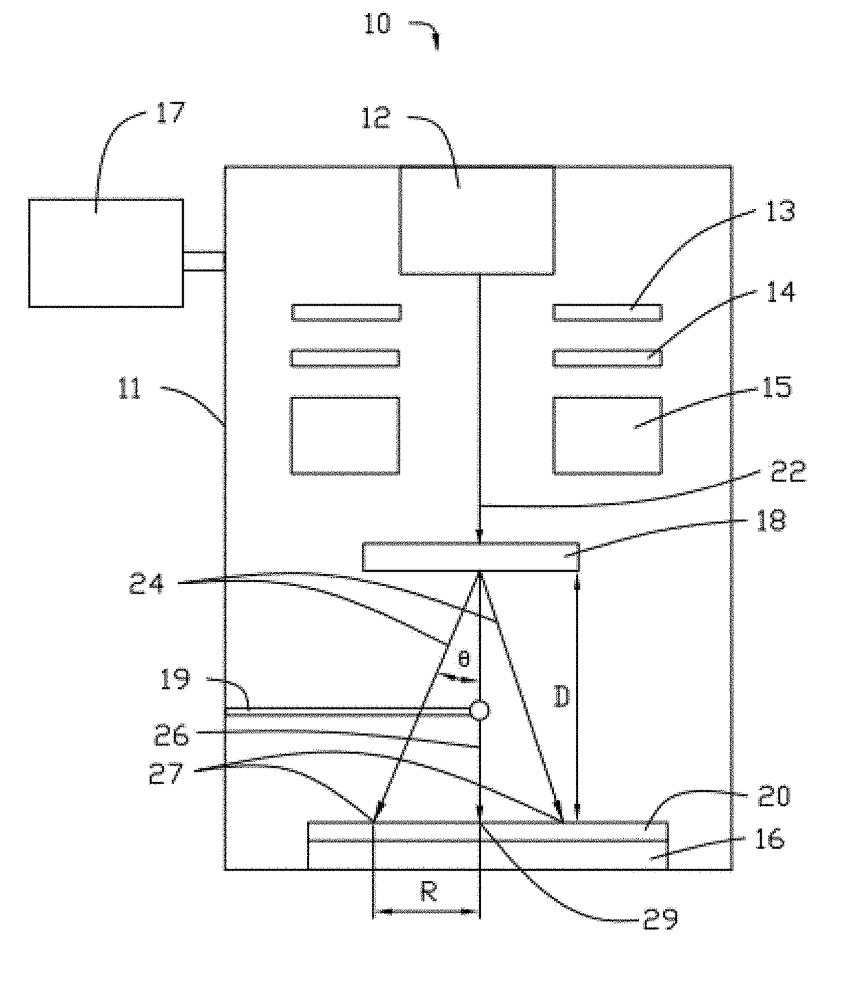
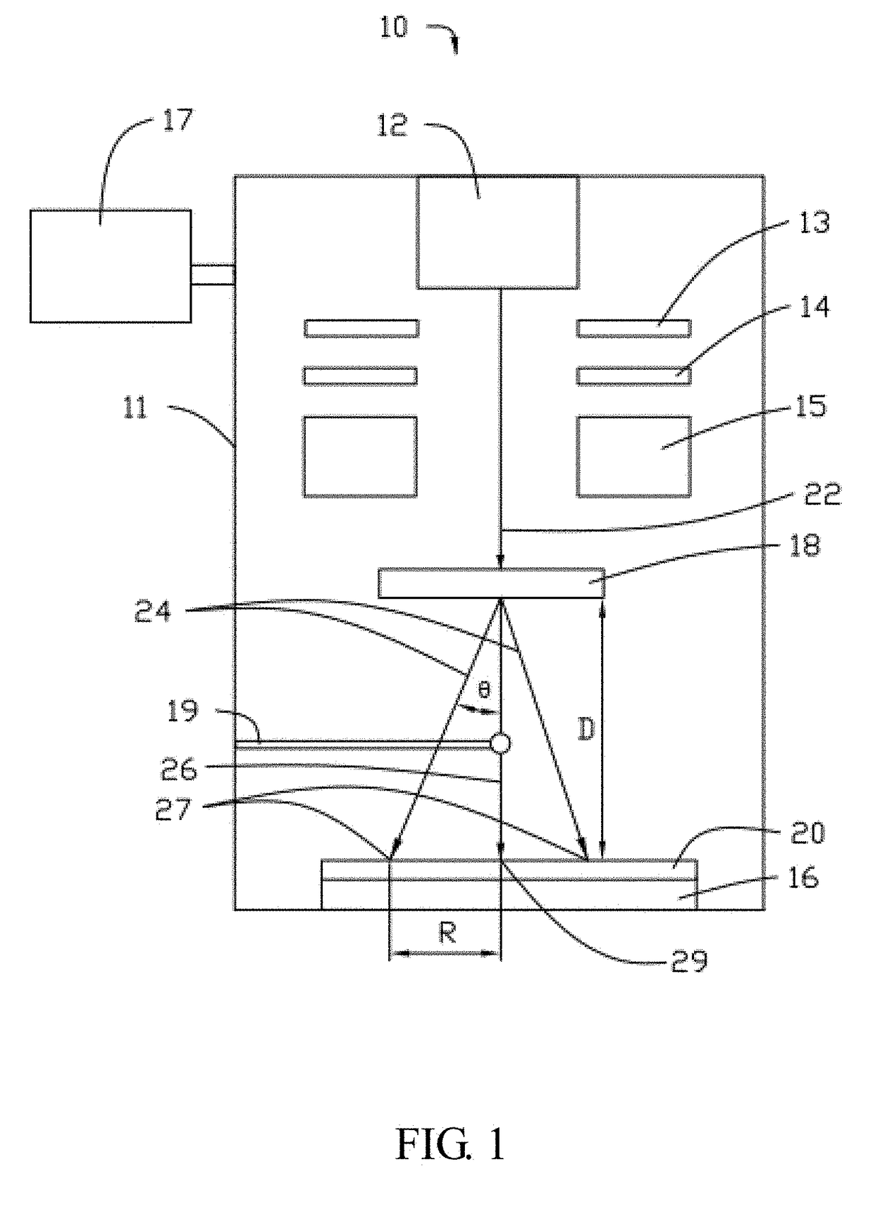
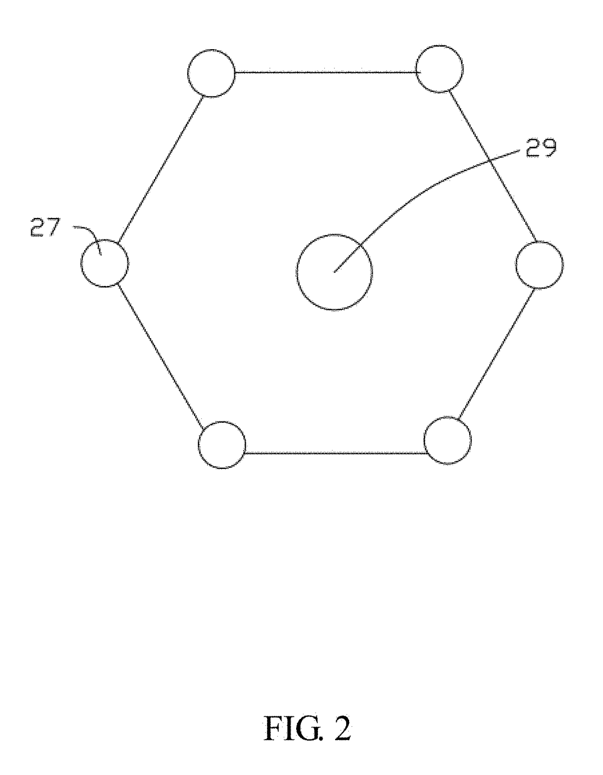
[0018]It will be appreciated that for simplicity and clarity of illustration, where appropriate, reference numerals have been repeated among the different figures to indicate corresponding or analogous elements. In addition, numerous specific details are set forth in order to provide a thorough understanding of the embodiments described herein. However, it will be understood by those of ordinary skill in the art that the embodiments described herein can be practiced without these specific details. In other instances, methods, procedures, and components have not been described in detail so as not to obscure the related relevant feature being described. The drawings are not necessarily to scale, and the proportions of certain parts may be exaggerated better illustrate details and features. The description is not to considered as limiting the scope of the embodiments described herein.

[0019]Several definitions that apply throughout this disclosure will now be presented. The term “couple...


PUM


Abstract

The disclosure relates to an electronic beam machining system. The system includes a vacuum chamber; an electron gun located in the vacuum chamber and used to emit electron beam; a holder located in the vacuum chamber and used to fix an object; a control computer; and a diffraction unit located in the vacuum chamber; the diffraction unit includes a two-dimensional nanomaterial; the electron beam transmits the two-dimensional nanomaterial to form a transmission electron beam and a plurality of diffraction electron beams; the transmission electron beam and the plurality of diffraction electron beams radiate the object to form a transmission spot and a plurality of diffraction spots.

Description

CROSS-REFERENCE TO RELATED APPLICATIONS[0001]This application claims all benefits accruing under 35 U.S.C. §119 from China Patent Application No. 201610405200.4, filed on Jun. 8, 2016, in the China Intellectual Property Office, the disclosure of which is incorporated herein by reference.BACKGROUND1. Technical Field[0002]The present disclosure relates to an electronic beam machining (EBM) system and a photolithography method based on electronic beam.2. Description of Related Art[0003]Electronic beam machining (EBM) is a method to treat a workpiece by the heat generated by the electron beam having high power density. The electronic beam machining can be used to for surface heat treatment, welding, etching, drilling, melting, or material sublimation.[0004]The electron emitted from the scorching cathode filament in a vacuum are accelerated at high voltage in a range from about 30 KV to about 200 KV and focused by the electromagnetic lens to form the electron beam having a power density ...

Claims


Application Information

Patent Timeline
IPC IPC(8): H01J37/30C01B32/182H01J37/302C01G39/06B82Y20/00H01J37/305H01J37/31H01J37/315H01J37/317
CPCH01J37/3002H01J37/302C01B32/182C01G39/06H01J37/3174H01J37/315C01P2004/24H01J37/3056B82Y20/00Y10S977/734Y10S977/755Y10S977/932H01J37/31H01J37/1472H01J37/243H01J37/30H01J2237/30472H01J2237/31B82Y35/00H01J37/305H01J37/06H01J2237/083
Inventor LIU, PENGZHAO, WEILIN, XIAO-YANGZHOU, DUAN-LIANGZHANG, CHUN-HAIJIANG, KAI-LIFAN, SHOU-SHAN
Owner TSINGHUA UNIV
Why Eureka
Try Eureka