Plasma generator apparatus

a generator and plasma technology, applied in the direction of chemical vapor deposition coating, electric discharge tubes, coatings, etc., can solve the problems of high deposition process time, low deposition speed, and deterioration of mass productivity, so as to achieve significant increase in deposition speed

Inactive Publication Date: 2017-12-21
JEHARA CORP
View PDF2 Cites 2 Cited by
  • Summary
  • Abstract
  • Description
  • Claims
  • Application Information

AI Technical Summary

Benefits of technology

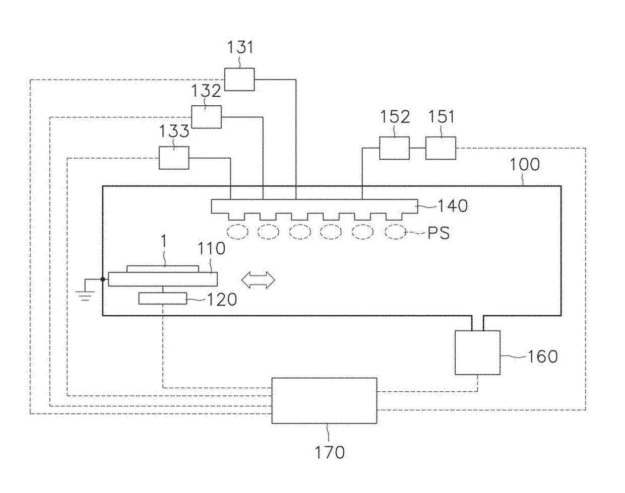
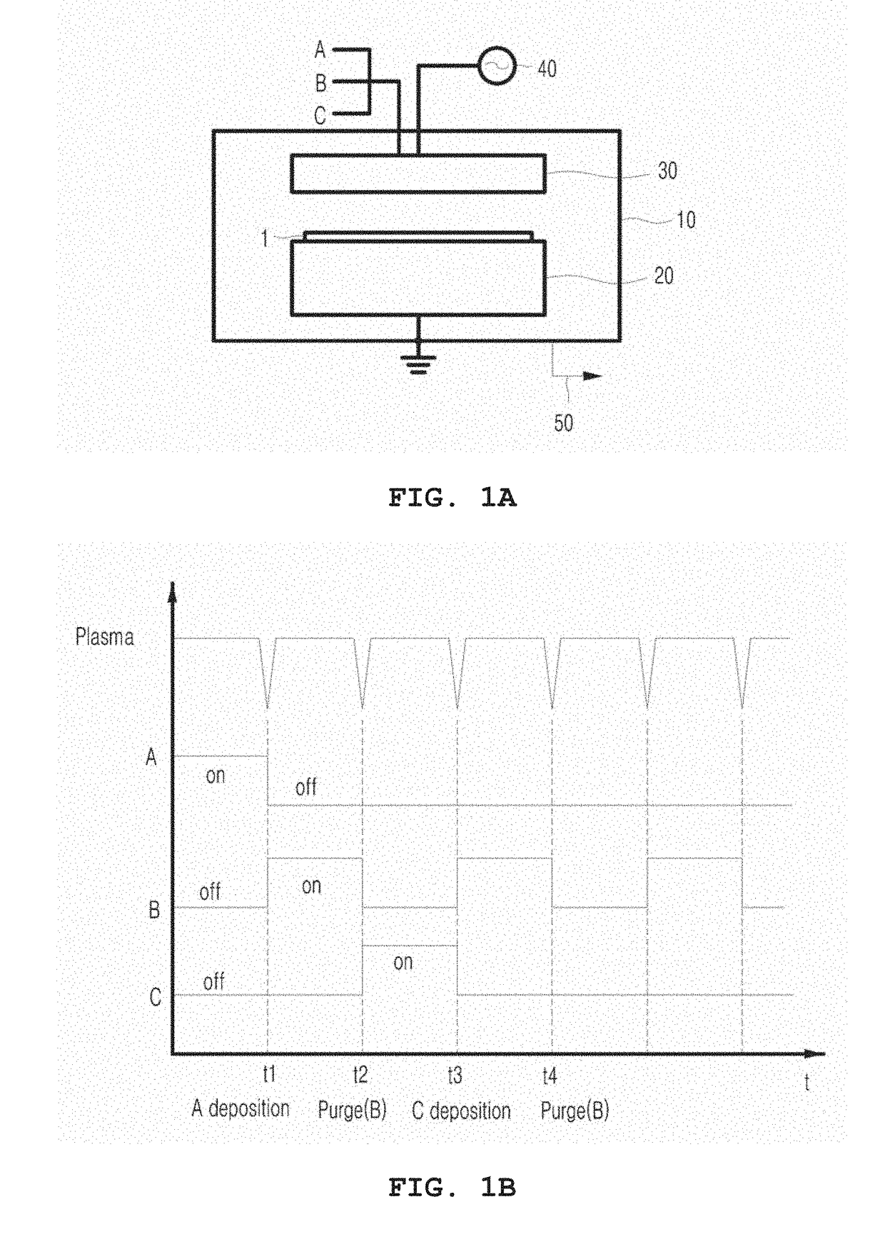
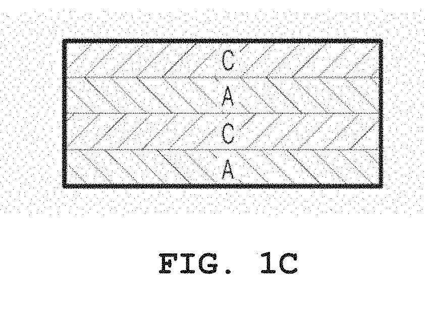
[0018]According to the exemplary embodiment of the present invention, in the plasma generator apparatus, the thin-film deposition is possible by injecting reaction gas and purge gas to the substrate in a local plasma atmosphere at a predetermined spatial period. Accordingly, the injection of different reaction gases is sequentially turned on / off, and as a result, the deposition may be made in a stable plasma state without the need of the injection. Particularly, in the local plasma atmosphere, while the plurality of reaction gases are injected with the purge gas, the thin-film deposition is possible, and as a result, as compared with a PEALD method in the related art, a deposition speed can be significantly increased.

Problems solved by technology

Recently, as a method for depositing a high-quality thin film at a low temperature, an atomic layer deposition (ALD) method has been frequently researched, and the ALD method is a method of depositing atoms sequentially layer by layer in atomic units and thus, the characteristics of the deposited thin film are excellent, but there is a disadvantage in that a deposition speed is low and mass productivity is deteriorated.
Further, the thin film deposition is made by sequentially injecting a plurality of reaction gases and thus there is a problem in that a lot of deposition process time is required.

Method used


Image

  • Plasma generator apparatus
  • Plasma generator apparatus
  • Plasma generator apparatus

Examples


Embodiment Construction

[0026]Specific structural or functional descriptions presented in exemplary embodiments of the present invention are made only for the purposes of describing the exemplary embodiments according the concept of the present invention and the exemplary embodiments according the concept of the present invention may be carried out in various forms. Further, it should not be interpreted that the exemplary embodiments are limited to the exemplary embodiments described in the present specification and it should be understood that the present invention covers all the modifications, equivalents and replacements within the idea and technical scope of the present invention.

[0027]Meanwhile, terms such as first and / or second, and the like may be used for describing various components, but the components are not limited by the terms. The terms may be used only for distinguishing one component from other components, for example, a first component may be referred to as a second component, and similar...


PUM

PropertyMeasurementUnit
temperatureaaaaaaaaaa
pressureaaaaaaaaaa
DC voltageaaaaaaaaaa

Abstract

Provided is a plasma generator apparatus for forming a thin film in local plasma atmosphere at a predetermined spatial period. The plasma generator apparatus includes an electrode body part 141, a plurality of gas supply ports 142 which protrude from the electrode body part 141 at predetermined pitch intervals to direct the substrate and have nozzle holes h1 electing the reaction gas, and a plurality of purge ports 143 which are dented with steps between the gas supply ports 142 and have exhaust holes h2 exhausting the reaction gas.

Description

RELATED APPLICATIONS[0001]This application claims the priority of Korean Patent Application No. 10-2016-0076416 filed on Jun. 20, 2016, in the Korean Intellectual Property Office, the disclosure of which is incorporated herein by reference.BACKGROUND OF THE INVENTIONField of the Invention[0002]The present invention relates to a plasma generator apparatus, and a thin film deposition apparatus and an atomic layer deposition (ALD) apparatus using the plasma.Description of the Related Art[0003]Recently, in order to manufacture a flexible display, an organic light-emitting diode (OLED) has received much attention, a flexible substrate has been used in manufacturing of the flexible display, and polyethylene terephthalate (PET) has been mainly used as a flexible substrate material.[0004]For deposit on the flexible substrate, the deposition needs to be made at a low temperature to prevent damage to an organic emission layer and generally, a recommended deposition temperature is within 100° ...

Claims


Application Information

Patent Timeline
Patent Type & Authority Applications(United States)
IPC IPC(8): H01J37/32C23C16/50C23C16/455
CPCH01J37/32568C23C16/45544H01J2237/332H01J37/3244C23C16/50C23C16/45536C23C16/45551C23C16/505H01J37/32091C23C16/4408C23C16/4412H01J37/32532H01J37/32834
Inventor KIM, HONGSEUB
Owner JEHARA CORP
Why Eureka
Try Eureka