Carbon dioxide gas shielded welding method for carbon steel pressure vessel

A carbon dioxide and pressure vessel technology, applied in welding equipment, welding medium, welding equipment, etc., can solve the problems of high welding efficiency, low welding efficiency, and unreliable welding quality, and achieve high production efficiency, fast deposition speed, and reduced The effect of labor intensity

Active Publication Date: 2019-01-22
YICHANG CITY RUIYANG MACHINERY MFG
View PDF7 Cites 0 Cited by
  • Summary
  • Abstract
  • Description
  • Claims
  • Application Information

AI Technical Summary

Problems solved by technology

[0004] The purpose of the present invention is to provide a carbon dioxide gas shielded welding method for carbon steel pressure vessels. The welding method is to weld the weld in layers and adopt different welding process parameters for each layer, so that the weld after welding can resist pressure. It has strong capability and high welding efficiency, which solves the technical problems of low welding efficiency and unreliable welding quality in the prior art of manual arc welding for pressure vessels.

Method used


Image

  • Carbon dioxide gas shielded welding method for carbon steel pressure vessel
  • Carbon dioxide gas shielded welding method for carbon steel pressure vessel
  • Carbon dioxide gas shielded welding method for carbon steel pressure vessel

Examples


Embodiment Construction

[0018] In order to make the technical means realized by the present invention, the creation features, the achievement of the purpose and the effect clearer and easier to understand, the present invention will be further elaborated below in conjunction with the accompanying drawings and specific embodiments:

[0019] As a preferred embodiment of the present invention, please refer to the appendix figure 1 and figure 2 :

[0020] A carbon dioxide gas shielded welding method for a carbon steel pressure vessel, comprising the following steps in sequence:

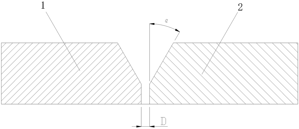
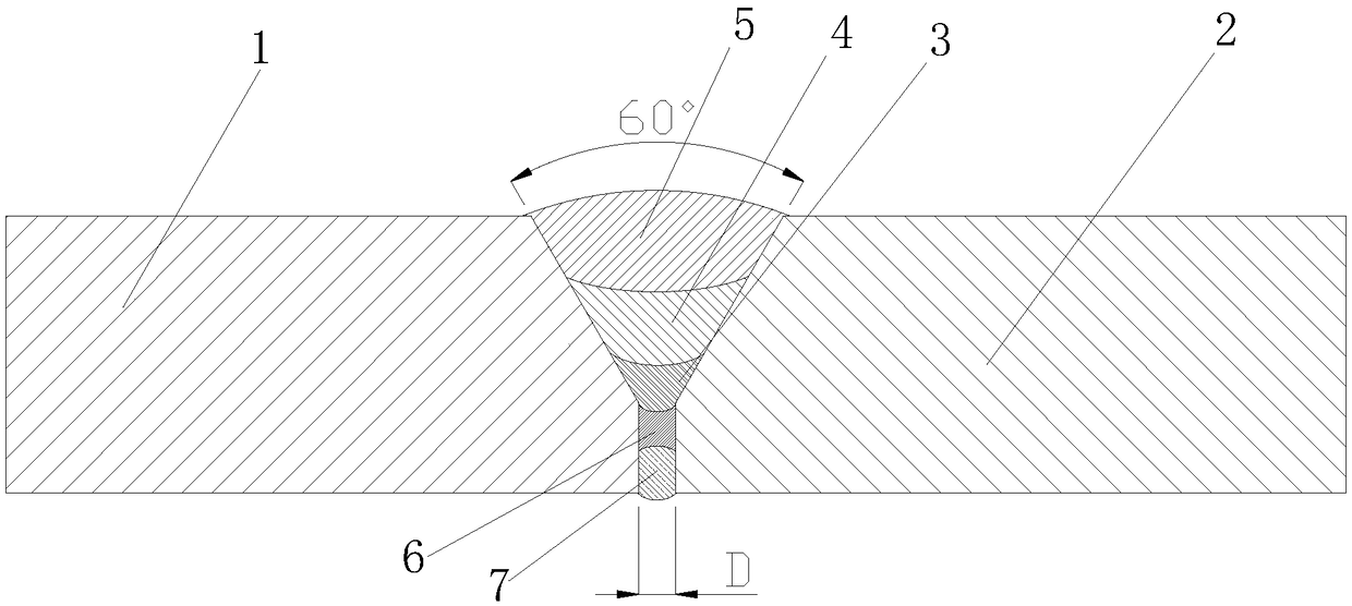
[0021] Step 1: Process the butt area of ​​the tube sections 1 and 2 of the carbon steel pressure vessel to be welded to form a V-shaped groove, the groove angle is 30° on one side, and the depth of the groove is 2 / 3 of the thickness of the base metal , blunt edge 1 ~ 2mm;

[0022] Step 2: Assemble the barrel sections so that the assembly gap is 1-2mm, and polish the area to be welded and the range of 20mm on both sides to th...


PUM


Abstract

The invention provides a carbon dioxide protective welding method of a carbon steel pressure vessel. The method comprises the following steps: grinding welding positions of base materials to form 30-degree grooves; pairing two base materials to be welded, wherein a gap between the two base materials is 1-2mm, and the alignment tolerance is not greater than 1mm; and sequentially welding a base layer, a filling layer, a surface covering layer, a back filling layer and a back surface covering layer of a welding seam according to the welding technological parameters of different welding layers. According to the method, a reasonable welding sequence and reasonable welding technological parameters are determined according to the characteristics of the pressure vessel; a welding heat effect area is narrow, so that the welding stress and deformation can be reduced, and the waste of welding fluxes can be avoided, and as a result, the manufacturing cost can be reduced, the welding efficiency can be improved, the welding quality can be ensured; moreover, the environmental pollution is reduced, so that the energy conservation, emission reduction and environment protection can be achieved; the surface of the welding seam welded by the welding method is fine in texture and nice in appearance, and the splashing is small, so that the appearance quality of the welding seam of the pressure vessel can be improved.

Description

technical field [0001] The invention relates to the technical field of pressure vessel manufacturing, in particular to a carbon dioxide gas shielded welding method for a carbon steel pressure vessel. Background technique [0002] With the rapid development of engineering welding technology, modern pressure vessels have also developed into a typical all-welded structure. Welding of pressure vessels has become the most important and critical link in the manufacturing process of pressure vessels, and the quality of welding directly affects the quality of pressure vessels. Because pressure vessels are easy to be hardened during welding, these hardened structures are very sensitive. Therefore, in the case of high rigidity or high restraint stress, cold cracks are likely to occur if the welding process is improper. The existing pressure vessel welding adopts electrode arc welding. , The welding seam is not beautiful and the manufacturing cost is high, the efficiency is low, the e...

Claims


Application Information

Patent Timeline
Patent Type & Authority Patents(China)
IPC IPC(8): B23K9/16B23K9/235B23K33/00B23K35/38B23K103/04B23K101/12
CPCB23K9/16B23K9/235B23K33/004B23K35/38B23K2101/12B23K2103/04
Inventor 李荣华
Owner YICHANG CITY RUIYANG MACHINERY MFG
Why Eureka
Try Eureka