Equipment and method for manufacturing copper alloy material

Active Publication Date: 2017-12-28
HITACHI METALS LTD
View PDF2 Cites 0 Cited by
  • Summary
  • Abstract
  • Description
  • Claims
  • Application Information

AI Technical Summary

Benefits of technology

The invention provides a way to make copper alloy material that doesn't have any blockages caused by the inclusions in the copper. This is done by using a special equipment and method during the manufacturing process.

Problems solved by technology

Since this requires removal of the blockage in the pouring nozzle, it is difficult to continuously operate the copper alloy manufacturing machine for long periods of time and thus difficult to manufacture a copper alloy material at high productivity.

Method used


Image

  • Equipment and method for manufacturing copper alloy material
  • Equipment and method for manufacturing copper alloy material
  • Equipment and method for manufacturing copper alloy material

Examples


Embodiment Construction

[0022]Copper Alloy Material Manufacturing Equipment

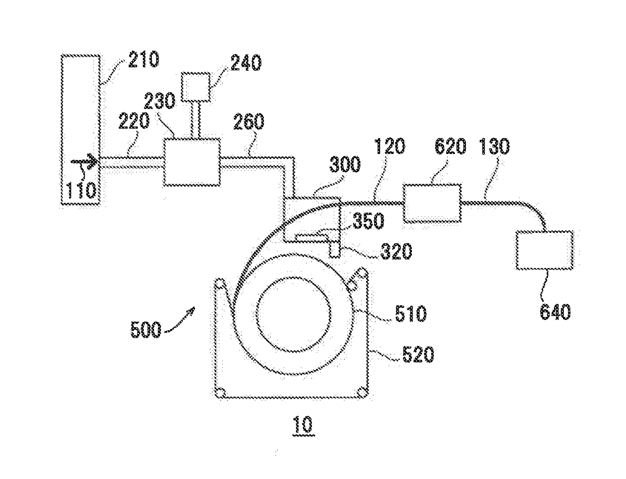
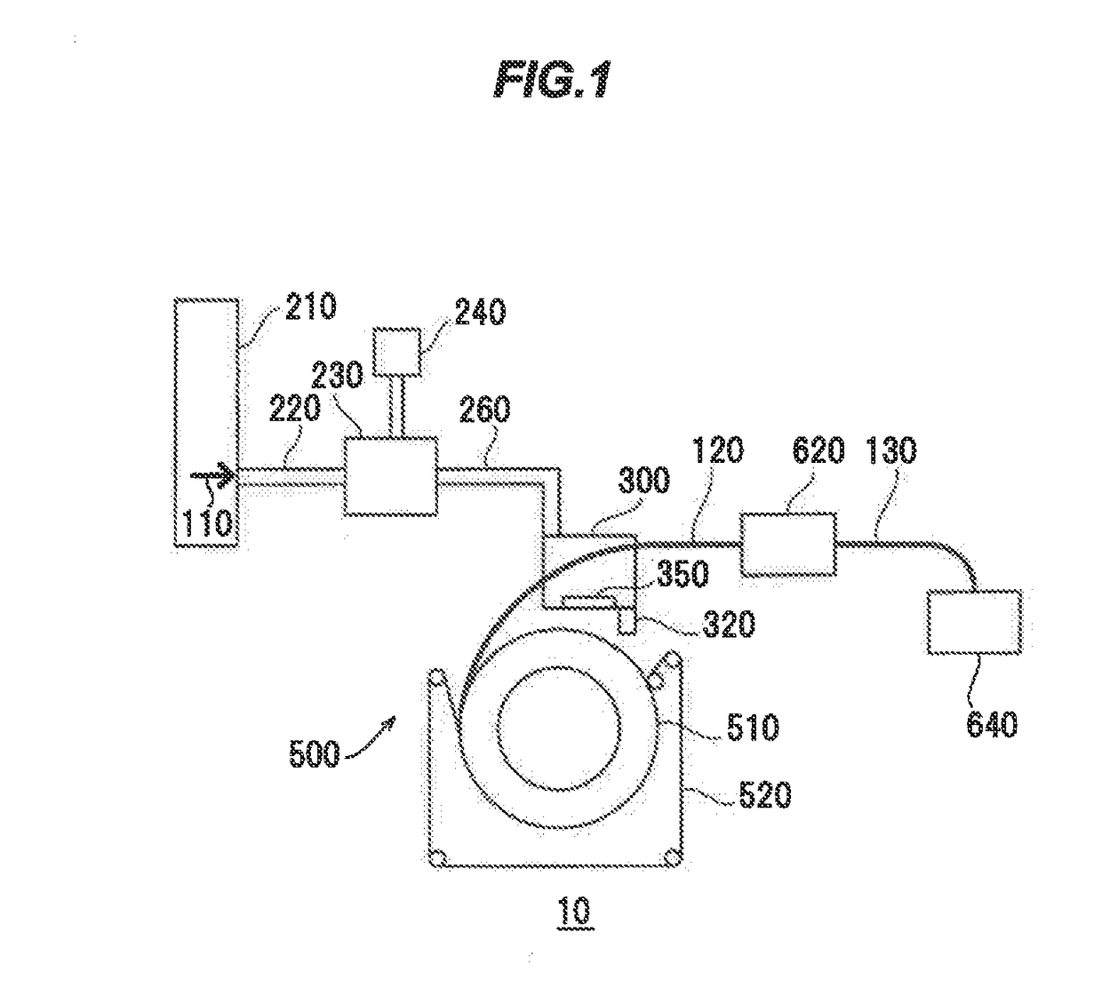
[0023]A copper alloy material manufacturing equipment in an embodiment of the invention will be described in reference to FIG. 1, FIG. 1 is a schematic configuration diagram illustrating a copper alloy material manufacturing equipment in the present embodiment.

[0024]The term “copper alloy material” as used herein is a collective term for wire rod and wire strand obtained by drawing the wire rod.

[0025]As shown in FIG. 1, a copper alloy material manufacturing equipment 10 in the present embodiment is configured as so-called continuous casting-and-rolling system (Southwire Continuous Rod system: SCR) for continuously casting and rolling a copper alloy material, and has, e.g., a smelting furnace 210, an upper pipe 220, a retaining furnace 230, an element adding means 240, a lower pipe 260, a tundish 300, a pouring nozzle 320, a continuous casting machine 500, a continuous rolling mill 620 and a coiler 640.

[0026]The smelting furnace 210 ...


PUM


Abstract

A copper alloy material manufacturing equipment for manufacturing a copper alloy material by continuously casting molten copper. The equipment includes an element adding means for adding a metal element to the molten copper, a tundish for holding the molten copper containing the metal element, a pouring nozzle connected to the tundish to feed the molten copper from the tundish, and a trapping member arranged inside the tundish and including a same type of material as at least one of an oxide of the metal element, a nitride of the metal element, a carbide of the metal element and a sulfide of the metal element.

Description

[0001]The present application is based on Japanese patent application No. 2016-126301 filed on Jun. 27, 2016, the entire contents of which are incorporated herein by reference.BACKGROUND OF THE INVENTION1. Field of the Invention[0002]The invention relates to an equipment and method for manufacturing a copper alloy material.2. Description of the Related Art[0003]As a method of manufacturing a copper alloy material, for example, a continuous casting and rolling method is known. In this method, firstly, molten copper is formed by melting a copper material in a smelting furnace. Next, a metal element (alloying element) such as titanium or magnesium is added to the molten copper. Next, the molten copper containing the alloying element is transferred to a tundish, and the molten copper in the tundish is fed to a continuous casting machine through a pouring nozzle. After that, the molten copper is rolled by the continuous casting machine while being cooled and solidified, thereby obtaining...

Claims


Application Information

Patent Timeline
IPC IPC(8): B22D11/116C22C1/02B21B3/00B22D11/00C22C9/00C22C1/10
CPCB22D11/116C22C1/02B22D11/004B21B2003/005C22C1/1036B21B3/003C22C9/00C22C1/0425
Inventor FUJITO, KEISUKEHATA, SHOHEITSUJI, TAKAYUKIKURODA, HIROMITSU
Owner HITACHI METALS LTD
Why Eureka
Try Eureka