Deep hydroconversion process using an extraction of aromatics and resins, with upgrading of the hydroconversion extract and raffinate in downstream units

a hydroconversion and extracting technology, applied in the field of deep hydroconversion of heavy hydrocarbon feeds, can solve the problems of reducing the availability time, limiting the maximum conversion which can be obtained in deep hydroconversion units, and unstable asphaltenes with a tendency to precipita

Inactive Publication Date: 2017-12-28
AXENS SA
View PDF7 Cites 11 Cited by
  • Summary
  • Abstract
  • Description
  • Claims
  • Application Information

AI Technical Summary

Benefits of technology

[0088]The advantage of the invention resides in the presence of the deasphalting unit upstream of the aromatics extraction, which means that an aromatic extract can be obtained with a low impurities content since these are found in the asphalt leaving deasphalting.

Problems solved by technology

The asphaltenes are unstable and have a tendency to precipitate in hot spots such as the furnaces and column bottoms (more particularly in the vacuum column).
As a consequence, the units and columns are periodically stopped for cleaning, which reduces their availability time.
In a typical refinery, the possible diluents such as the heavy residual fraction (slurry) from catalytic cracking, are available in limited quantities and are thus a factor limiting the maximum conversion which can be obtained in deep hydroconversion units.
Since the atmospheric residue obtained from the hydroconversion is not deasphalted in the process described in that patent, the extract obtained from the extraction unit is likely to contain asphaltenes, which could lead to a degradation of the hydroconversion performances in the case of recycling it to the hydroconversion.
However, none of the prior art documents can overcome all of the problems mentioned.

Method used


Image

  • Deep hydroconversion process using an extraction of aromatics and resins, with upgrading of the hydroconversion extract and raffinate in downstream units
  • Deep hydroconversion process using an extraction of aromatics and resins, with upgrading of the hydroconversion extract and raffinate in downstream units
  • Deep hydroconversion process using an extraction of aromatics and resins, with upgrading of the hydroconversion extract and raffinate in downstream units

Examples


example

[0173]The feed used in this example had the composition detailed in Table 1. It was a vacuum residue of the “Urals” type, and thus a vacuum residue obtained from crude oil originating from Russia.

TABLE 1Composition of the feed used (“Urals” type vacuum residue)PropertyUnitValueDensity—1.003Viscosity at 100° C.cSt540Conradson carbon% by wt15.0C7 asphaltenes% by wt4.0Nickelppm by wt70Vanadiumppm by wt200Nitrogenppm by wt5800Sulphur% by wt2.7540° C.− cut*% by wt10.0*Cut containing products with a boiling point below 540° C.

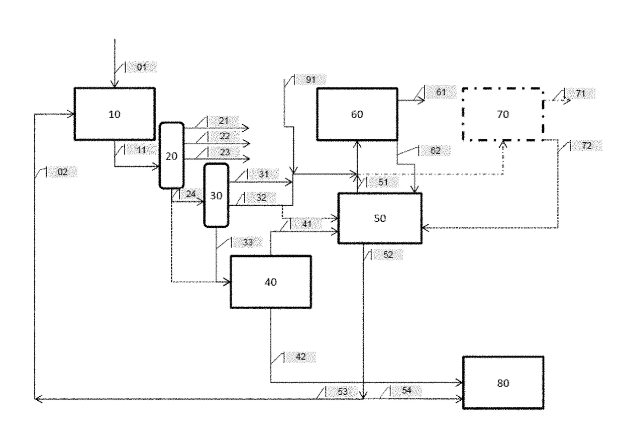
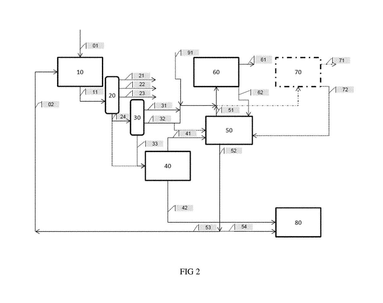
[0174]In this example, the feed was used in the process in accordance with the invention (FIG. 2) with neither hydrocracking in 60 nor catalytic cracking in 70, and thus also without adding vacuum distillate obtained by straight run crude oil distillation (SR VGO) 91 at the inlet to the hydrocracking and / or catalytic cracking steps.

[0175]However, in accordance with another variation, certain products obtained may subsequently be sent to a hydrocracking step, in parti...


PUM

PropertyMeasurementUnit
temperatureaaaaaaaaaa
pressureaaaaaaaaaa
catalytic bed temperatureaaaaaaaaaa

Abstract

Process for deep conversion of heavy hydrocarbon feed, which includes:a) ebullated bed hydroconverting the feed in at least one three-phase reactor containing at least one supported hydroconversion catalyst;b) atmospheric fractionating effluent from a) producing gasoline fraction, gas oil cut, and atmospheric residue;c) vacuum fractionation of at least a portion of the atmospheric residue to obtain a vacuum gas oil fraction and an unconverted vacuum residue fraction;d) deasphalting at least a portion of the unconverted vacuum residue fraction with an organic solvent obtaining a hydrocarbon cut depleted in asphaltenes, termed deasphalted oil, and residual asphalt; ande) liquid / liquid extraction on the hydrocarbon cut depleted in asphaltenes extracting aromatics by a polar solvent producing an extract enriched in aromatics and resins and a raffinate depleted in aromatics and resins, at least a portion of the extract sent to the inlet of the hydroconversion as an aromatic diluent.

Description

FIELD OF THE INVENTION[0001]The invention relates to the field of the deep conversion of heavy hydrocarbon feeds in order to obtain upgradable hydrocarbon cuts such as liquefied petroleum gas (or LPG), gasolines or naphthas, kerosene, gas oil and oils.[0002]The invention pertains to process flow diagrams which can be used to improve the performances of conversion units by introducing an extraction of the aromatics.[0003]As a general rule, refineries comprise a unit for deep hydroconversion of residue followed by an atmospheric fractionation then a vacuum fractionation and downstream, a catalytic cracking unit and / or a hydrocracking unit. Optionally, a unit for deasphalting residue not converted during the hydroconversion is also present.[0004]Deep hydroconversion processes are used in the refinery to transform mixtures of heavy hydrocarbons into easily upgradable products. They are usually principally used to con vert heavy feeds such as oil cuts or heavy synthetics, for example res...

Claims


Application Information

Patent Timeline
Patent Type & Authority Applications(United States)
IPC IPC(8): C10G67/04C10G65/12C10G69/04
CPCC10G67/0409C10G69/04C10G2300/1096C10G2300/44C10G65/12C10G67/04C10G67/049C10G7/00C10G7/06C10G21/003C10G21/06
Inventor LE COZ, JEAN-FRANCOISMOREL, FREDERIC
Owner AXENS SA
Why Eureka
Try Eureka