
Cell culture container, automatic cell culture apparatus, liquid container, robot hand, and robot system

Active Publication Date: 2017-12-28
DENSO WAVE INC +1
View PDF2 Cites 10 Cited by
  • Summary
  • Abstract
  • Description
  • Claims
  • Application Information

AI Technical Summary

Benefits of technology

The present invention relates to a robot system for closing liquid containers. The system uses a robot hand to grasp and rotate the cap of a container. However, when the grasp is incomplete or friction occurs between the robot hand and the cap, wear debris may be produced on the cap's surface. To prevent this, the system detects if the cap is at an incorrect position and grasps it in the opposite direction, rotating it to the correct position to close the container. This prevents wear debris from causing contamination inside the working chamber where the robot arm performs tasks. The technical effect of the invention is to prevent contamination and improve the efficiency and accuracy of the robot system for closing liquid containers.

Problems solved by technology

For example, if the cultivated cells are contaminated by another person's cells, the cultivated cells are no longer usable.
Accordingly, when a robot hand grasps and rotates the cap of a container, with the container body being fixed, if the grasped state is incomplete and friction is caused between the robot hand and the cap, the surface of the cap made of resin may be abraded by the robot hand to thereby produce wear debris.

Method used


Image

  • Cell culture container, automatic cell culture apparatus, liquid container, robot hand, and robot system
  • Cell culture container, automatic cell culture apparatus, liquid container, robot hand, and robot system
  • Cell culture container, automatic cell culture apparatus, liquid container, robot hand, and robot system

Examples


first embodiment

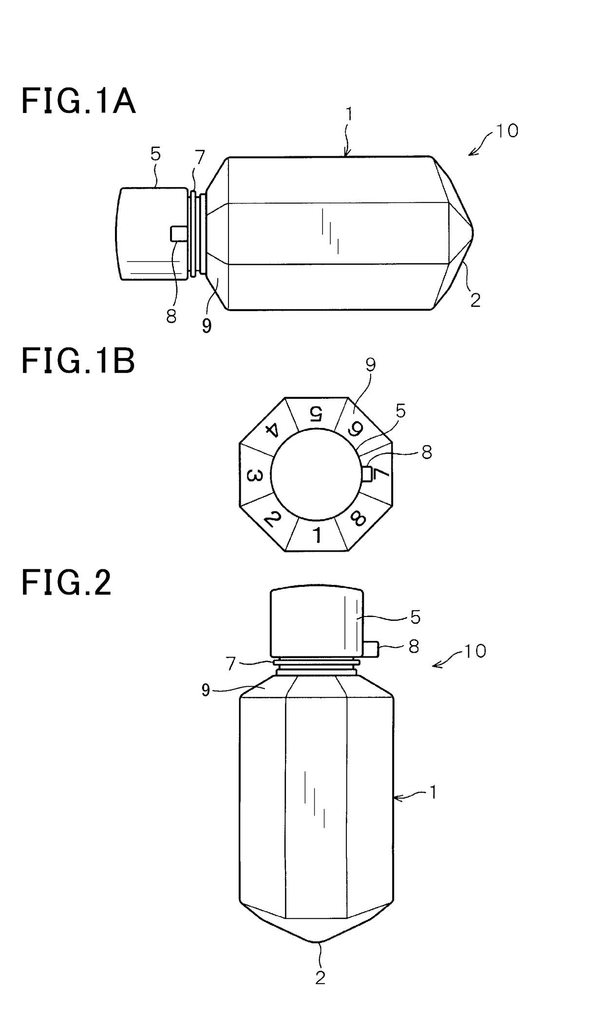
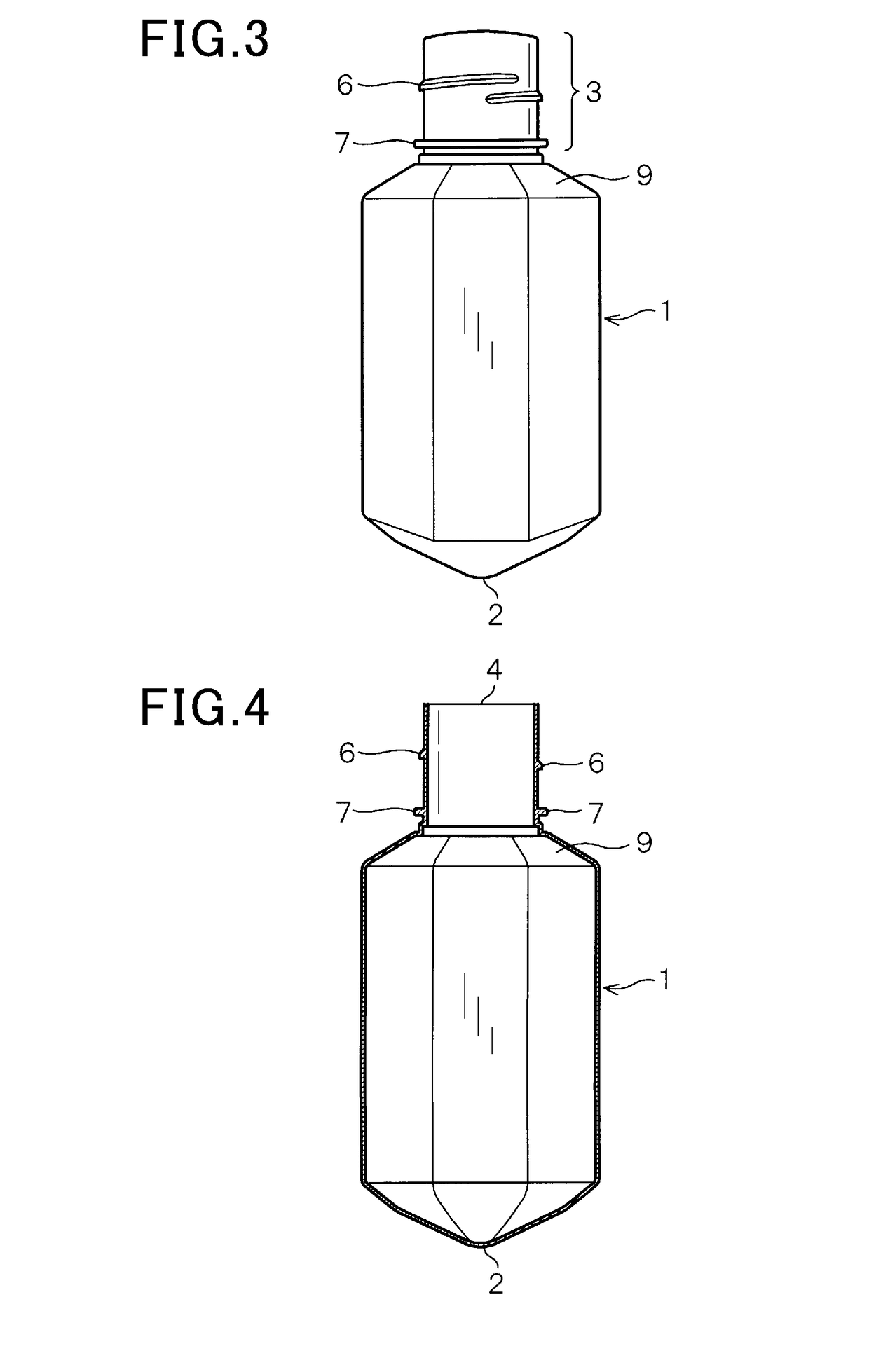
[0057]The following description addresses a first embodiment of the present invention. As shown in FIGS. 1A and 1B, and FIGS. 2 to 4, a bottle 10 serving as a cell culture container of the present embodiment has a body 1 in an octagonal prism shape including a closed lower end part 2, and an upper end part facing the lower end part 2. The upper end part is provided with a cap neck 3 which is in an annular shape and has a diameter smaller than that of the lower end part 2. The body 1 in an octagonal prism shape is formed of eight planar surfaces in which two opposed surfaces are substantially parallel to each other. Since the bottle 10 also serves as a tube for centrifugation, the closed lower end part 2 is in a conical or octagonal conical shape. The body 1 corresponds to the container body. The cell culture container is an example of the liquid container of the present embodiment.

[0058]The cap neck 3 has an upper end face serving as an opening portion 4. The cap neck 3 has an outer...

second and third embodiments

[0090]In the following description, the components identical with or similar to those of the first embodiment are given the same reference numerals for the sake of omitting duplicate description. The following description is focused on the differences from the first embodiment. The second and third embodiments exemplify variations of the position indicator provided to the bottle body. FIGS. 14 and 15 show a bottle 41 according to the second embodiment. The bottle 41 includes a prism body 42 having a position indicator 43. The position indicator 43 is configured to two line segments which are part of a straight line passing through a center C of the body 42. Specifically, the position indicator 43 is configured to a line segment 43a which is defined between the outer periphery of the cap neck 3 and the outer periphery of the body 42, and another line segment 43b which is defined similarly to the line segment 43a.

[0091]In the second embodiment, the following process is taken when det...

fourth embodiment

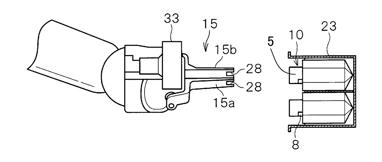
[0103]FIGS. 18A and 18B show a robot hand 61 of the fourth embodiment. As shown in these figures, the robot hand 61 is provided with two claws 61a, 61b, similarly to the robot hand 15 of the first embodiment. Unlike the first embodiment, however, these claws 61a, 61b are not provided with the recesses 28. The robot hand 61 with this shape can also grasp and rotate the cap 5, with part of a side portion of the claw 61a, for example, being abutted against the protrusion 8 of the cap 5, without causing friction therebetween.

[0104]The present invention should not be construed as being limited to the embodiments described above or illustrated in the drawings, but may be modified or extended as follows.

[0105]For example, in the first embodiment, the recess 28 may be provided to only one of the claws.

[0106]The length of the projection 8 may be changed as appropriate in conformity with individual design.

[0107]The number of claws of the robot hand may be three or more.

[0108]The bottle body i...


PUM


Abstract

A bottle includes a body, a cap mounted to a cap neck of the body. The cap has an outer peripheral portion which is provided with a protrusion. Around the cap, there is provided a position indicator indicating whether the cap is at a correctly closed position, based on the positional relationship between the protrusion and the position indicator.

Description

CROSS-REFERENCE TO RELATED APPLICATION[0001]This application is based on and claims the benefit of priority from earlier Japanese Patent Application No. 2016-127618 filed Jun. 28, 2016, the description of which is incorporated herein by reference.BACKGROUND OF THE INVENTIONTechnical Field of the Invention[0002]The present invention relates to a cell culture container, an automatic cell culture apparatus, a liquid container, a robot hand handling the container, and a robot system provided with the robot hand.Related Art[0003]In recent years, robots are being applied to worksites which are associated with medications or medical services. With this trend, isolators used for cell culture tasks and the like have been put into the market. Such an isolator includes a work area where a robot arm is placed so that an operator can externally give commands to the robot arm for cell culture tasks and the like. For example, a patent literature JP 4550101 B discloses a configuration in which mate...

Claims


Application Information

Patent Timeline
IPC IPC(8): C12M1/36B25J19/02B25J15/00C12M1/24C12M1/00C12M3/00
CPCC12M41/48C12M23/08C12M23/38B25J19/023C12M23/50B25J15/0028C12M23/46B25J15/08B25J21/00
Inventor KAMIYA, KOJISAITO, WATARUNAGAIKE, KAZUHIRO
Owner DENSO WAVE INC
Features
  • Generate Ideas
  • Intellectual Property
  • Life Sciences
  • Materials
  • Tech Scout
  • Unparalleled Data Quality
  • Higher Quality Content
  • 60% Fewer Hallucinations
Learn More