Wearable device for safety monitoring of a user

a wearable device and user technology, applied in the direction of alarms, instruments, etc., can solve the problems of communication set-up, and achieve the effects of low power consumption, high accuracy, and small siz

Active Publication Date: 2017-12-28
TITAN CO LTD
View PDF11 Cites 27 Cited by
  • Summary
  • Abstract
  • Description
  • Claims
  • Application Information

AI Technical Summary

Benefits of technology

[0024]A precise, gesture-based, safety monitoring wearable device for a user having, (a) a cover 1, (b) side keys, (c) a laser etching 3, (d) a heart-rate monitor 4, (e) a charging port 5, (f) a controller, (g) a mobile device, (h) a Remote Server, (i) a battery, (j) an SOS battery, (k) distress signal, (l) a light emitting diode (LED), (m) a vibration motor, (n) 9-axis inertial measurement unit (IMU), (o) one or more alert signals, (p) a Bluetooth and, (q) a processor. Additionally, a GPS sensor and a GSM modem are available in the Wearable that works independently. The cover is located on top front portion. The laser etching, the heart-rate monitor and the charging port are on the backside of the wearable device. The battery is molded into a design for maximum safety. The SOS battery reserve is used to send the distress signal. The light emitting diode has a TFT display screen to display time under normal operating conditions. The vibration motor is located away from the 9-axis inertial measurement unit and is configured as a silent alarm using a vibration module such that the motor configured to vibrate upon generation of a distress Gesture to indicate to a user that the alert signal has been sent to registered emergency numbers of the user. The alert signal from the user is in the form of Gestures, and the IMU is utilized to get 3D position and orientation of the wearable device that aids in extracting meaningful Gestures. The controller is a microcontroller which is capable of storing necessary instructions required for ge

Problems solved by technology

A drawback associated with the wearable emergency alert device as disclosed in '547 is that two sets of communication take place, one from the wearable member to the mobile phone an

Method used


Image

  • Wearable device for safety monitoring of a user
  • Wearable device for safety monitoring of a user
  • Wearable device for safety monitoring of a user

Examples


Embodiment Construction

[0037]The present invention relates to a wearable device for safety monitoring of a user. The wearable device upon detection of a distress signal sends an alert signal along with the location data to the registered emergency numbers of the user. Here, the distress signal is generated either upon detection of a distress Gesture, upon pressing a distress button continuously by the user for a certain period, upon forceful removal of the wearable device, upon accident detection or free fall detection of the user.

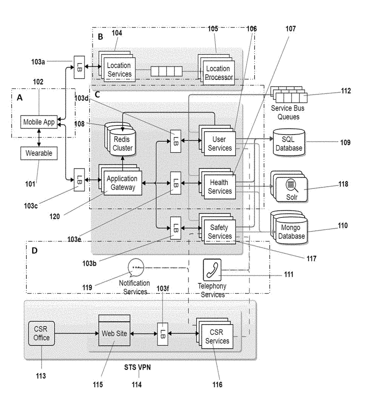
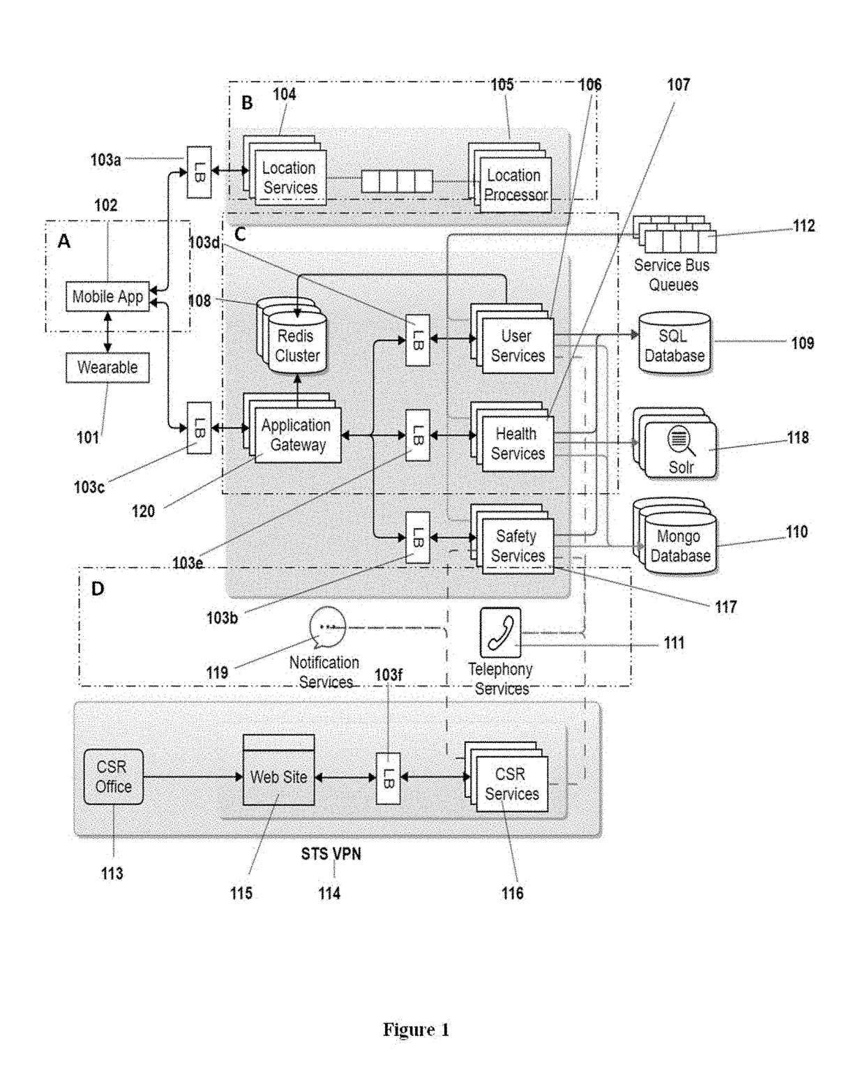
[0038]FIG. 1 is the overall system diagram of the present invention that consists of a Wearable A, Location services B, Services C, Customer services D, Service Bus Queues 112, a SQL Database 109, Solar search Engine 118, Mongo Database 110, Telephony services 111, Notification services 119, and one or more Load Balancers. The Wearable A includes a Wearable 101 and a Mobile application 102 which are integrated via Load Balancers 103a, 103b, 103c, 103d, 103e with different servic...


PUM


Abstract

A precise, gesture-based, safety monitoring system, method and device. The present invention comprises a controller, wherein the controller upon detection of a distress signal, sends an alert signal along with the Location information of the user to a Remote Server. The Remote Server, upon receiving an alert signal sends an SMS and e-mail along with the Location information to a Mobile device of the registered emergency numbers of the user and responds in real-time.

Description

STATEMENT OF RELATED APPLICATIONS[0001]This patent application claims priority on and the benefit of U.S. Provisional Patent Application No. 62 / 355,284 having a filing date of 27 Jun. 2016.BACKGROUND OF THE INVENTION[0002]Personal safety is an important concern in our society. Individuals may face danger or emergency situations when they are in a home, workplace or while traveling. In emergency situations, such as an accident, heart attack, brain stroke, abduction or molestation, carrying a cell phone in hand and informing to his or her well-wishers becomes difficult for an individual.[0003]To overcome the problem mentioned above, emergency alert devices were introduced. The emergency alert devices are popular among the elderly citizens who are subject to falling or suffering from strokes and heart attacks. In general, the existing emergency alert devices comprise a wearable device and a base unit. In emergency scenarios, the user presses a button on the wearable device, which sends...

Claims


Application Information

Patent Timeline
IPC IPC(8): G08B25/01G08B21/04G08B25/00G08B27/00G08B25/10
CPCG08B25/016G08B25/10G08B21/0446G08B27/008G08B21/0492G08B25/001G08B25/004G08B21/0453G08B25/08
Inventor NERAVATI, RAJA SEKHARGANGALAKURTI, MANOHARPANJALA, DILEEP KUMAR
Owner TITAN CO LTD
Why Eureka
Try Eureka