Calibration and Monitoring for 3-Axis Magnetometer Arrays of Arbitrary Geometry

a technology of magnetometer array and calibration procedure, applied in the direction of magnetic measurement, instruments, measurement devices, etc., can solve the problems of inability to perform routine visual inspection, many structures are not easy to inspect, and many metal components of structures are susceptible to defects, so as to increase the reproducibility of the calibration procedure and reduce the time

Active Publication Date: 2018-01-04
CHARLES STARK DRAPER LABORATORY
View PDF9 Cites 43 Cited by
  • Summary
  • Abstract
  • Description
  • Claims
  • Application Information

AI Technical Summary

Benefits of technology

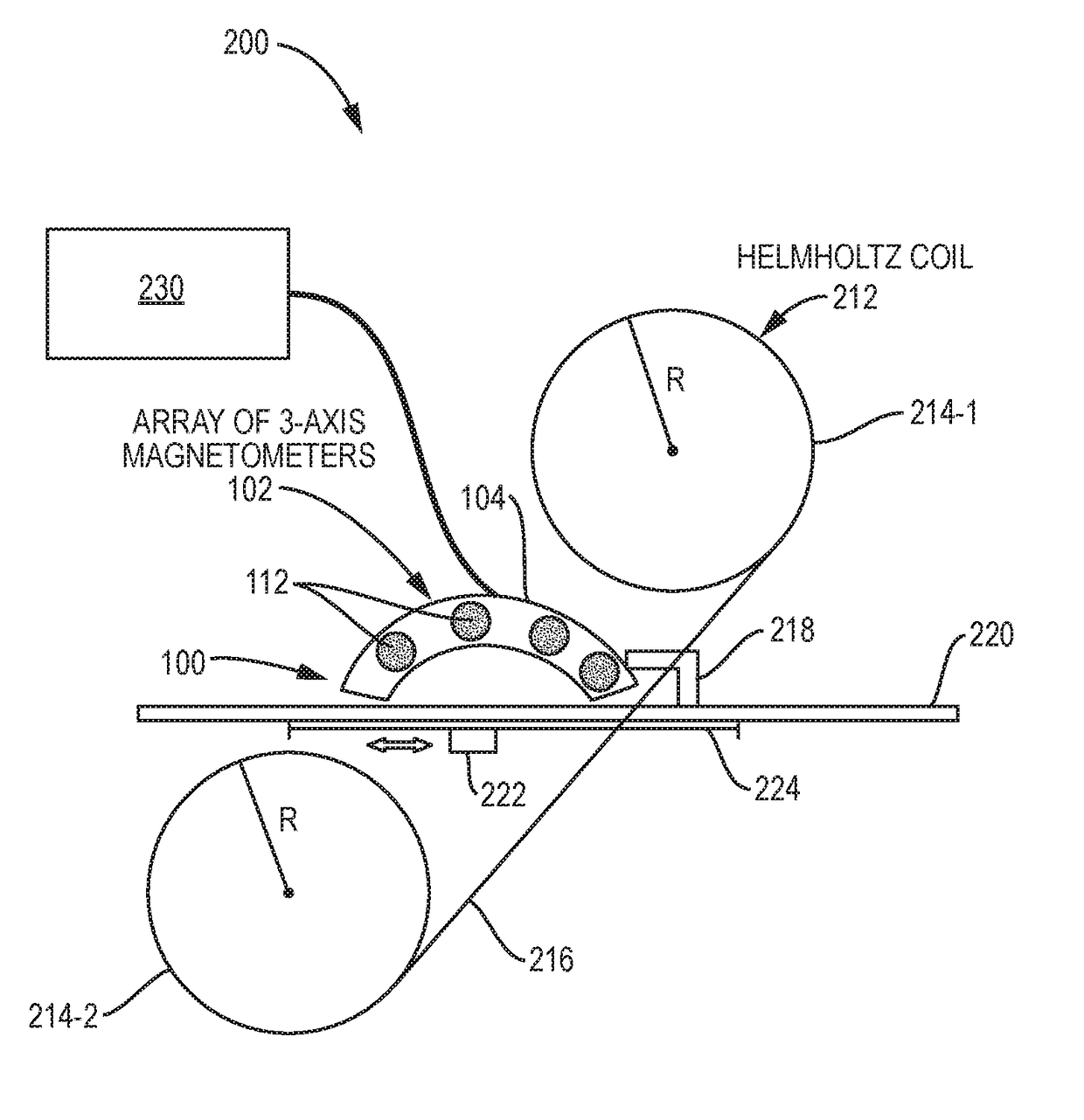
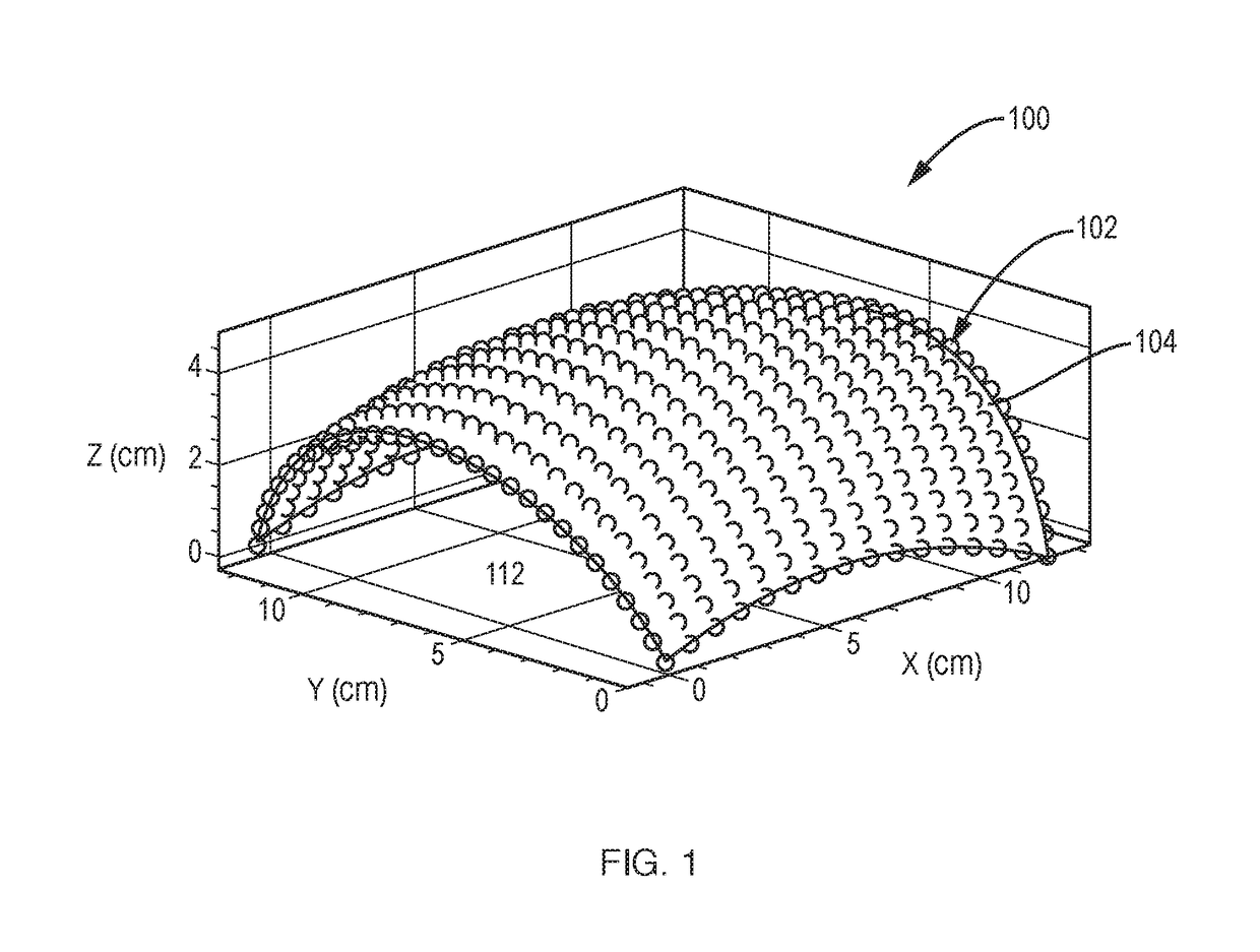
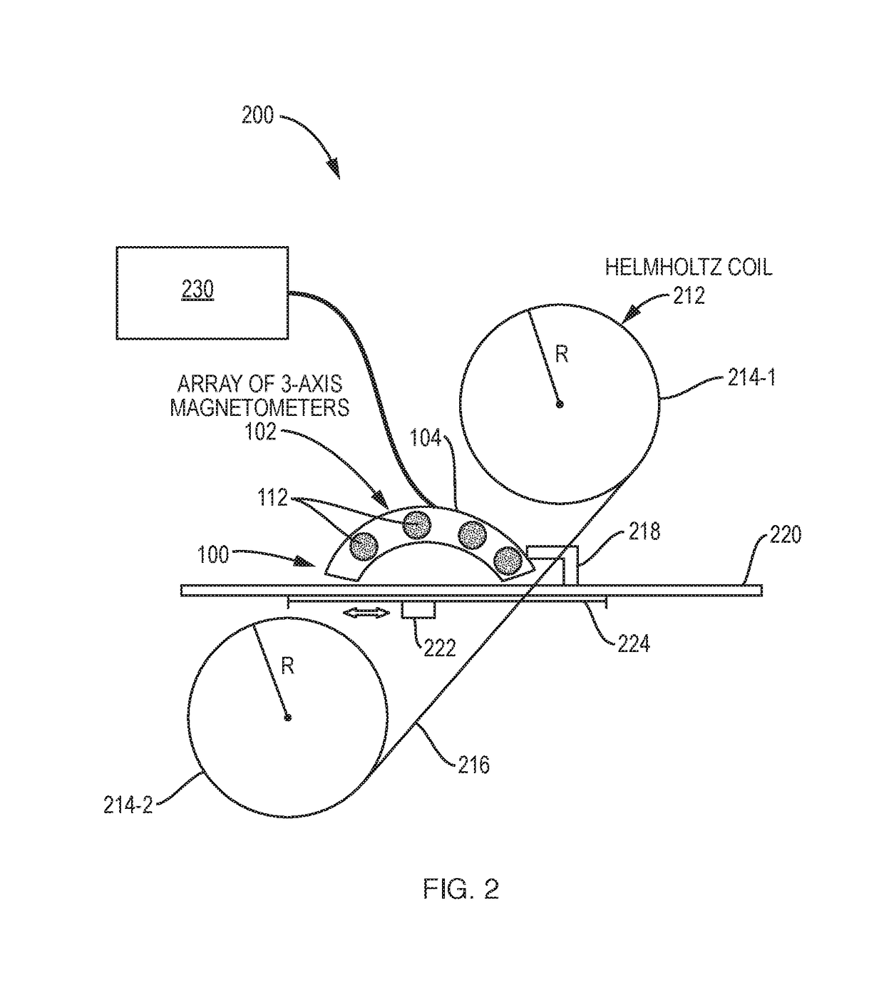
[0007]The present invention concerns a system and method for calibrating rigid arrays of multiple 3-axis magnetometers as might be used to analyze structures containing ferromagnetic material. Calibration refers to determining scale factor, bias, relative position, and orientation of each magnetometer in the rigid array. Once the parameters are determined, actual magnetic field value at the magnetometer location can be simply related to m

Problems solved by technology

Metal components of structures are susceptible to defects, such as due to imperfect manufacture, corrosion, fatigue, wear, damage, etc.
However, many structures are not easy to inspect due to being buried underground or under the sea, or due to being embedded within other materials such as concrete.
For large structures containing metal components

Method used


Image

  • Calibration and Monitoring for 3-Axis Magnetometer Arrays of Arbitrary Geometry
  • Calibration and Monitoring for 3-Axis Magnetometer Arrays of Arbitrary Geometry
  • Calibration and Monitoring for 3-Axis Magnetometer Arrays of Arbitrary Geometry

Examples


Embodiment Construction

[0024]The invention now will be described more fully hereinafter with reference to the accompanying drawings, in which illustrative embodiments of the invention are shown. This invention may, however, be embodied in many different forms and should not be construed as limited to the embodiments set forth herein; rather, these embodiments are provided so that this disclosure will be thorough and complete, and will fully convey the scope of the invention to those skilled in the art.

[0025]As used herein, the term “and / or” includes any and all combinations of one or more of the associated listed items. Further, the singular forms and the articles “a”, “an” and “the” are intended to include the plural forms as well, unless expressly stated otherwise. It will be further understood that the terms: “includes”, “comprises”, “including” and / or “comprising”, when used in this specification, specify the presence of stated features, integers, steps, operations, elements, and / or components, but do...


PUM


Abstract

A system and method for calibrating rigid and non-rigid arrays of 3-axis magnetometers as disclosed. Such arrays might be used to analyze structures containing ferromagnetic material. The calibration determines scale factor and bias parameters of each magnetometer in the array, and the relative orientation and position of each magnetometer in the array. Once the parameters are determined, the actual magnetic field value at the magnetometer location can be simply related to magnetometer measurements. The method and system can be used to calibrate an array of 3-axis magnetometers in aggregate as opposed to individual magnetometers. This is critical in large arrays to increasing reproducibility of the calibration procedure and decreasing time required to complete calibration procedure.

Description

RELATED APPLICATIONS[0001]This application claims the benefit under 35 USC 119(e) of U.S. Provisional Application No. 62 / 356,591, filed on Jun. 30, 2016 which is incorporated herein by reference in its entirety.BACKGROUND OF THE INVENTION[0002]Metal components of structures are susceptible to defects, such as due to imperfect manufacture, corrosion, fatigue, wear, damage, etc. To prevent catastrophic failure of such structures, metal components may be visually inspected to identify defects before a failure occurs. However, many structures are not easy to inspect due to being buried underground or under the sea, or due to being embedded within other materials such as concrete. For large structures containing metal components, such as bridges and tunnels, routine visual inspection may be impractical or too costly to perform.[0003]Many ferromagnetic objects, including steel pipe, act as weak permanent magnets even when not intentionally magnetized; for example, magnetic dipoles in stee...

Claims


Application Information

Patent Timeline
IPC IPC(8): G01R33/00G01R33/02G01N27/82
CPCG01R33/0023G01N27/82G01R33/0206G01R33/0035G01R35/00
Inventor SORENSEN, MICHAELBABCOCK, PHILIPJOHNSON, CORTPATEL, NEIL SUNIL
Owner CHARLES STARK DRAPER LABORATORY
Why Eureka
Try Eureka